
![]()
Robot hand
Introduction
The Savox company has a special device called SAVOX TRICS Communication Controller. This device has 2 versions: a simplified one with 2 buttons and a complex one with up to 8 buttons (6 on the front and 2 side buttons). Each button serves a different purpose, along with multiple pre-defined sequences including pressing and holding multiple buttons, resulting in different commands. The maximum number of buttons required in a sequence can be up to 5 buttons at a time. Also, there are requirements that request to hold a button for up to 20 seconds.
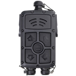
Figure 1: SAVOX TRICS Controller
To solve these problems, we introduce a handy gadget that can press those buttons in a specified sequence programmed beforehand. This device consists of a 4×3 matrix solenoids and 4 side solenoids, all powered by a power supply box. The solenoids are properly selected, each having a pull-push force of 5N, making it capable of pressing the button flawlessly.
The device receives commands from the user’s Raspberry Pi and executes the information received, resulting in pressing a button in the pre-defined sequence. The button-pressing sequences are programmed correspondingly to the given order provided by the Savox company.
Additionally, a holder is also developed to hold the TRICS controller. The holder is capable of holding the TRICS controller’s weight while also keeping the controller within range of the device’s reach.
Objective
The project presents a “Robot hand” device that can fulfill the requirements from the SAVOX company – to automatically press the buttons on the TRICS communication controller in a pre-defined sequence. Additionally, a holder is also created to carry the TRICS controller.
The device is expected to correctly press the TRICS controller’s buttons according to the pre-defined sequence. It is also required for the device to be robust enough to reach the TRICS controller in a fixed range. This range is determined between the device and the holder, which is responsible for holding the weight of the TRICS controller, while maintaining the distance between the device and the controller.
The main component used to press the buttons is the solenoid. A 5×3 matrix of solenoids is included in a so-called “Solenoid box”, associated with 2 side solenoids, making the device capable of pressing up to 8 buttons in multiple specified sequences. These sequences are pre-programmed in a given order by the Savox Company and stored in the user’s Raspberry Pi, which is the primary communication method of the design. The device will receive power from a power supply box to execute the information received from the user’s Raspberry Pi, and then proceed to press the buttons according to the sequences obtained. The instructions are visible on the user interface.
Some advanced features include LEDs to give notification when the device completes a sequence/task. The LEDs are visible at a fixed distance determined by the company. A speaker is also included to test the microphone from the TRICS controller. The speaker can make a sound to program recordings to TRICS.
Design
This section presents 2 main designs of any mechanical project: Hardware and Software.
Hardware
The picture below is a 3D model for our device.
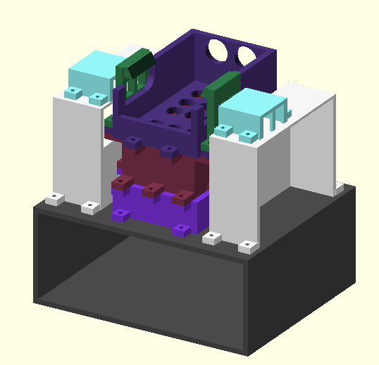
Figure 2: 3D model of the device
The device contains 3 major components: TRICS holder (top), Solenoid box (middle), and General box.
All our final 3D-models can be found from GitLab.
TRICS holder
After 4 versions, we create the final version of the TRICS holder. This TRICS holder is on top of the solenoid box, and its main purpose is to hold the TRICS controller in range for the solenoid to press the buttons on the controller accordingly.
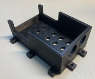
Figure 3: TRICS holder
Solenoid box
The box is built to be capable of carrying 15 solenoids and the outside dimensions were assembled based on the size of TRICS.
In the final version, the solenoid box was split into two separate parts: the upper part is the actual solenoid box which contains all the solenoids; the lower part includes the necessary empty space under the solenoids and is also linked with the general box. The design idea was to minimize the amount of necessary support material for quick and effective printing, while still having enough space to fit all 15 solenoids.
PCB design
We used KiCad to design our own schematic of the final circuit for the PCB, which connects all 16 solenoid circuits together. Below is the final schematic of our solenoid circuit.
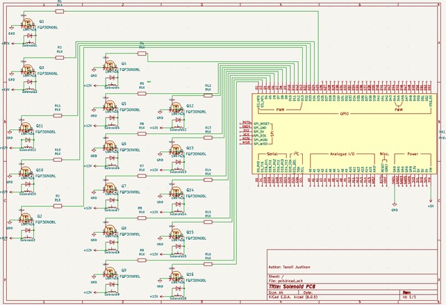
Figure 4: Final schematic of the circuit
We decided to design and build our own PCBs to house all the electronics needed to run the solenoids. Having the electronics on a PCB makes the construction smaller and makes it easy to connect and disconnect wires due to a clear layout if for example, one solenoid needs to be replaced.
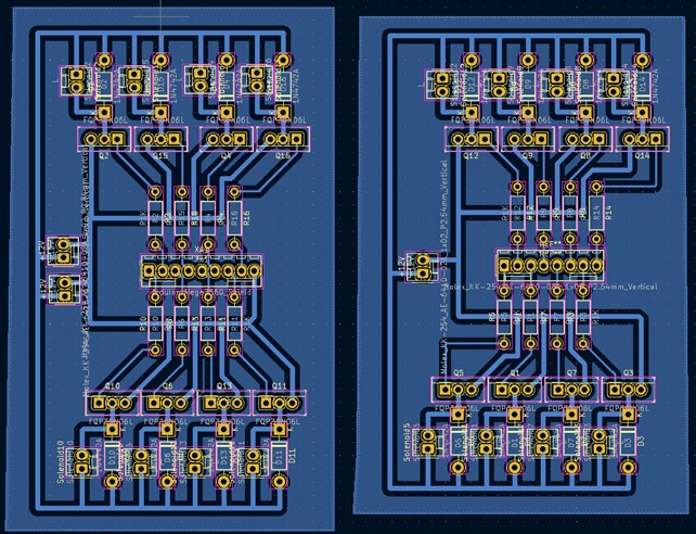
Figure 5: Final board design
The board was split into two parts for physical placement reasons. A power supply is connected to one board and a wire is run through the power supply housing to the other board. Eight cables are connected to each board from the Arduino Mega, as well as the ground the wire of Arduino is connected to one board. The solenoids can draw up to 1 Amp of current, so the power connections are wider than the logic connections.
Software
Arduino code that our device uses can be found from GitLab.
Final device
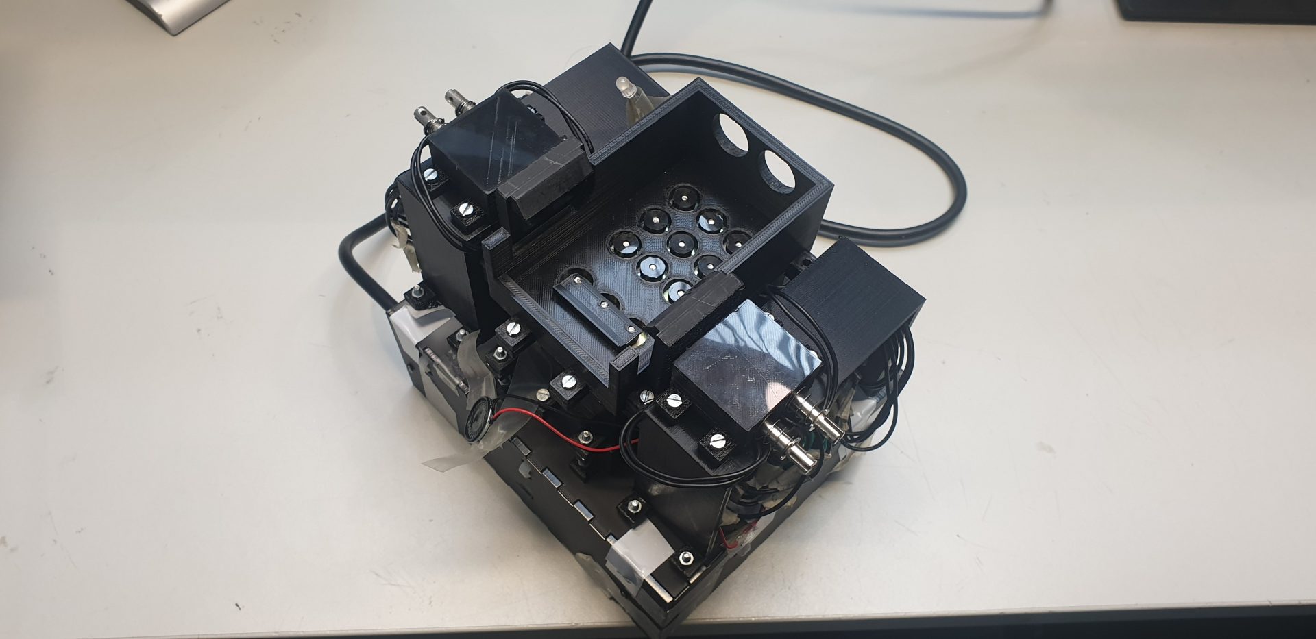
Figure 6: Final design without TRICS controller
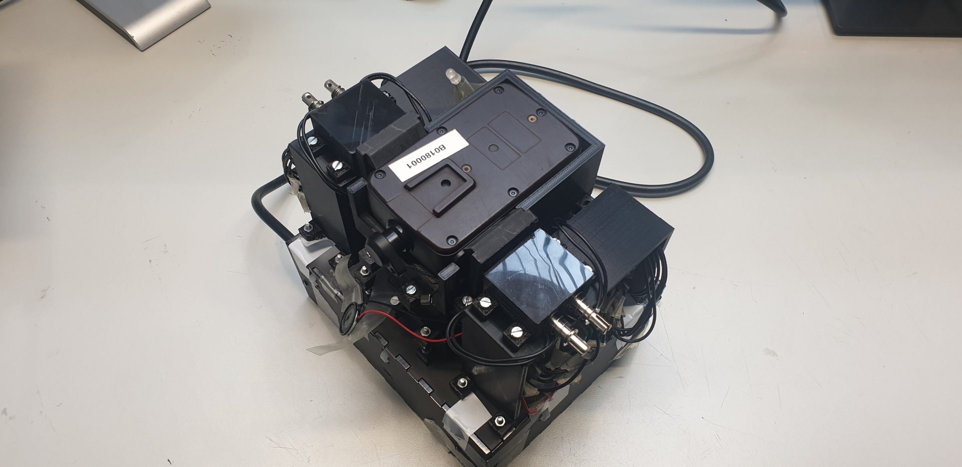
Figure 7: Final design including TRICS controller
Here are some videos that demonstrate how our device works:
Raspberry codes that are used in those demos can be found from GitLab.
Link:
- Gitlab: https://version.aalto.fi/gitlab/robot-hand/robot-hand
- Final report: https://docs.google.com/document/d/1YZCfVhajyPFK1wHpL_yboBfSqT2AeRfyxJRzCK2ElC8/edit?usp=sharing
Team:
Taneli Juutinen, Aalto University, student of Mechanical Engineering
Minh Le, Aalto Univeristy, student of Digital System and Design
Jenni Marttinen, Aalto University, student of Electronics and Electrical Engineering
Janna Lappalainen, Aalto University, student of Mechanical Engineering
Licensing: MIT License.