
![]()
ActiveAhead Radio Mapper Van
Objective
Helvar produces smart lighting control systems that consist of bluetooth controlled lighting nodes and sensors. ActiveAhead is this type of self-learning lighting control system, which can be used to optimize the lighting of every space.
In an office space, there might exist hundreds or even thousands of intelligent lighting fixtures. When these fixtures are installed, the identity of a fixture is not known, and a person needs to manually match each fixture to a specific ID. Our objective is to make an autonomous vehicle which drives around this space while scanning the BLE (Bluetooth Low Energy) beacons of the lighting fixtures. By measuring the ID and signal strenght (RSSI) of each fixture, it is possible to approximate the distance to each fixture based on the RSSI value. By taking measurements from different points, it is possible to approximate the position of each fixture with multilateration. This position can then be inserted into the floor plan.
By utilizing an autonomous vehicle for the mapping of fixtures, a lot of manual work can be avoided.
Hardware design
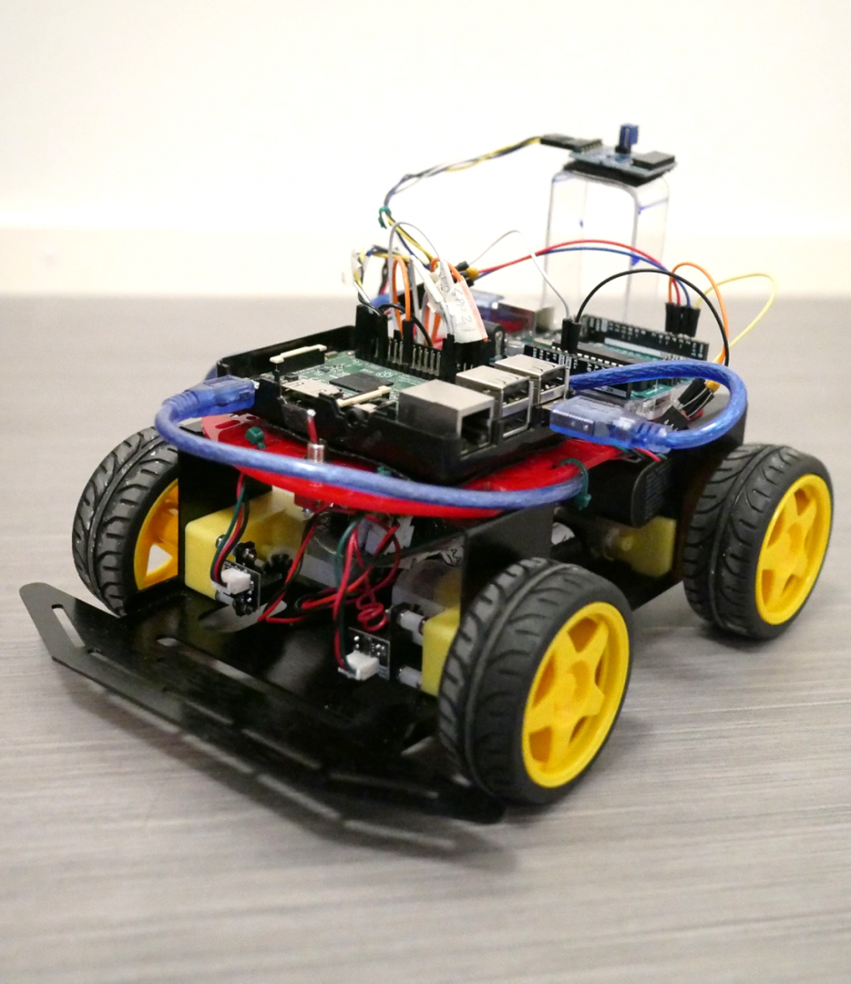
We decided to build the autonomous vehicle around the DFRobot Baron-4WD1 mobile robot platform. The kit includes the vehicle frame, DC motors, gearbox, wheels, and rotary encoders. We chose this platform as it is relatively cheap and provides plenty of space for adding our own components. Furthermore, the platform uses DC motors which do not require any advanced driving circuitry. Finally, the platform includes two rotary encoders for the wheels, which allows for accurate measurements of the distance driven.
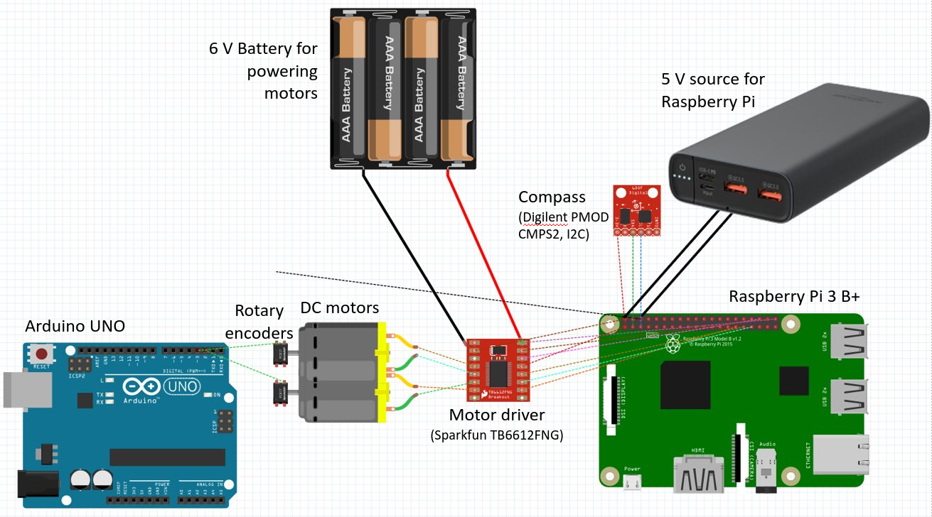
The vehicle is controlled with a Raspberry Pi 3 B+, from which we can give driving instructions for the vehicle and observe the direction of the vehicle with a compass module. Driving instructions are transmitted to the DC motors via the Sparkfun motor driver IC TB6612FNG2.
The vehicle is also equipped with an Arduino Uno, which is responsible for monitoring interrupts from the wheel’s rotary encoders in order to measure the distance travelled. The need to have the interrupt monitoring on a separate microcontroller comes from the fact that it was not possible to get reliable interrupt detection on the Raspberry Pi.
Power to the DC motors is fed from 5 NiMh batteries connected in series, providing a 6 V source. The rest of the electronics is powered from a regulated 5 V portable power bank.
Software design
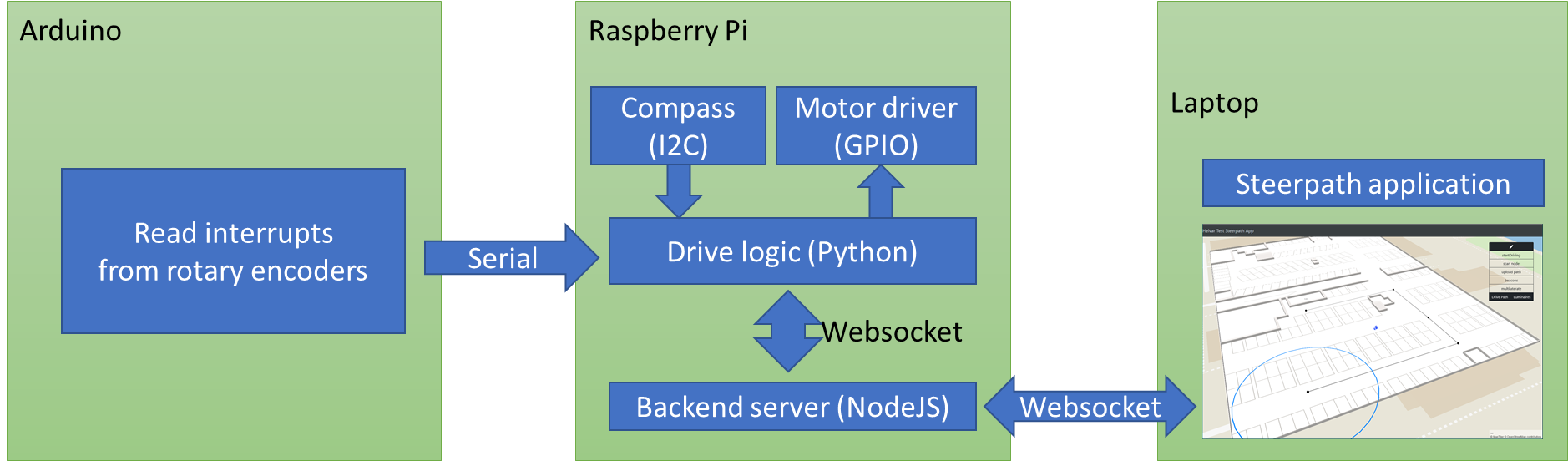
The software consists of multiple separate software components:
-
- NodeJS server handling bluetooth scanning, communication, storing and serving data
- Python component handling driving logic and communication with sensors
- Arduino that interfaces with analog sensors
- A web application for configuring the vehicle, setting a route for the vehicle and for displaying scan results in a map
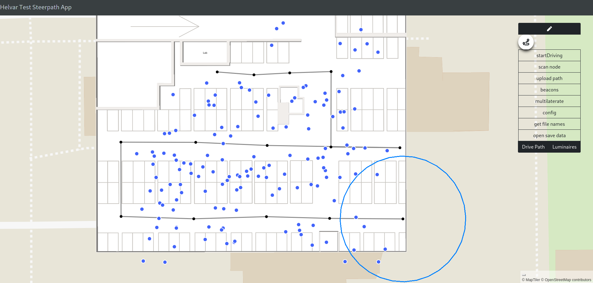
The front-end is built on top of an example application provided by Helvar that uses steerpathmap for rendering floor plans of indoor spaces on a map. The test space we have access to in Keilaniemi is already modeled in steerpathmap.
The application allows the user to plan a route for the vehicle by clicking on the map to set up a series of path nodes that the vehicle travels to. Once the user is satisfied with the planned path, they can send the instructions to the vehicle. At each node, the vehicle stops and scans for surrounding BLE beacons, recording the measuring position and the strength of the signal. These readings are passed back to the frontend if a socketIO connection is active. All readings are also stored in the Raspberry Pi for later use, for example if the client application is not connected.
The application also provides the tools for visualizing the measured data. For example, the user can inspect how an individual beacon was measured from each measuring point, and the positions the lamps are approximated to be at. The user is also provided with the ability to offset the path nodes if the measurements spots the vehicle drove to do not match those planned.
Node.js is used in the backend for scanning BLE luminaire nodes, serving the frontend application, storing and serving saved scan data and communicating with both the frontend and the vehicle logic through a Socket.IO connection.
Python is used to handle all tasks that are related to the driving of the vehicle. While it could have made sense to also use Node.JS for vehicle automation, it was decided to use Python instead as the handling of the Raspberry Pi’s GPIO pins is much more documented for the Python programming language than for Node.js.
The complete list of tasks that are handled by the Python vehicle automation include:
-
- Continuously listen for serial data sent by the Arduino.
- Continuously listen for incoming messages from the Node.JS backend on the socketIO connection.
- Continuously listen for keyboard input on the SSH session using the curses library.
- When a driving instruction is received, measure the vehicle’s heading using the compass to calculate in which direction to make a turn, then make the turn, then begin driving forward.
- When driving, continuously monitor the rotary encoder values to:
- stop driving when the target distance is reached.
- apply compensation if the distance travelled by the left and right wheels is not the same.
- Read values from the compass using I2C and convert the raw values from the compass to a heading.
In order to perform multiple tasks simultaneously, multithreading is used. For example, the tasks of listening for serial data and listening for keyboard input is split into separate threads. For listening on incoming messages on the Socket.IO connection, an event handler is registered which executes a predefined function each time a message is received.
The Arduino is used for the purpose of reading the interrupts created each time a rotary encoder passes an index point. The Arduino Uno supports registering interrupt handlers on pins 2 and 3, which is enough to register interrupts for the left and right rotary encoders separately. Each time an interrupt is registered on either pin 2 or 3, a counter is incremented for either the left or the right side. The values of these counters are then transmitted to the Raspberry Pi each 50 ms using the serial port.
Team
Olavi Karppelin, student of Electrical Engineering at Aalto Univesity
Panu Liesiö, student of Computer Science at Aalto University
Johan Rabb, student of Computer Science at Aalto University