
![]()
Objective:
The expected output of the project include devices that irrigate plants automatically and software to control them. The widget is targeted to improve the office environment by reducing the effort to water the plants manually and will be used by the office workers. The devices and the software will be implemented on the existing ActiveAhead system and user interface will be included in the ActiveTune Computer.
From the user’s point of view, controlling the devices and getting data from the sensors should be easy and intuitive. It should be obvious by using the user interface what each device is capable of as well as how to control it. Any error and/or status messages should be easy to understand so that the user has a clearer idea of the possible steps required to fix the problem. This has also to do with the fact that the main user group, which is mainly office staff, is not expected/needed to have any in depth knowledge of the underlying infrastructure (more generally people want “stuff to just work”).
The results of the project can be demonstrated by setting up the network and controlling/setting the devices.
Design:
High-level overview
The solution consists of three parts:
- The plant unit responsible for keeping the water level at a set level
- The protocol used for communication between the plant unit and the user interface
- The user interface through which the user can control the unit
The plant unit
Initial design:
Final design:
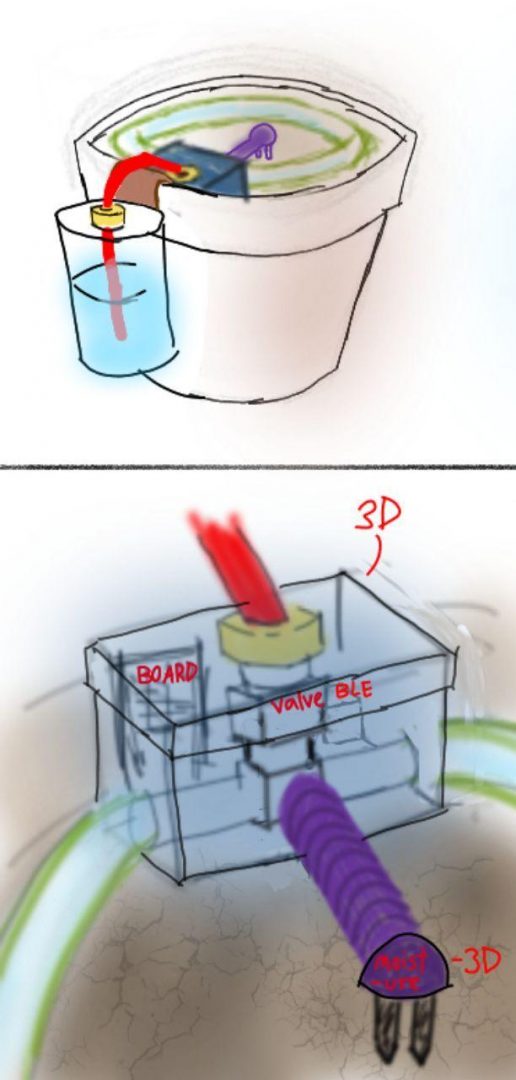
The plant unit is the physical part of the project. It’s job is to monitor the soil moisture and to keep it at some set level. It also allows the user to modify its settings and query its status by using the user interface.
The main parts making the plant are the water tank and the watering mechanism, the soil moisture sensor, the ble-to-serial converter, and the power supply. The microcontroller in the unit gathers samples for the soil moisture sensor and if needed adds more water into the pot in order to increase the moisture level. It also informs the user if the water tank is empty and keeps a limited log of the history of the moisture level in the pot.
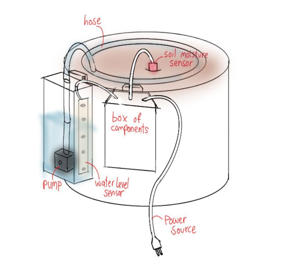
1. Tank
We installed a plastic tank that can hold up to 1.6 Litres of water. There is a pump at the bottom of the tank which is attached to a hose. The hose comes out from the lid and is attached to a round hose that distributes the water evenly. The water level sensor is also located along the inner wall of it, and the wires come out from the lid into the box of components. The tank is intended to be put along the pot’s side using an attached hook near the lid. As a finished product, the user will choose the size of the tank according to the size of their plant.
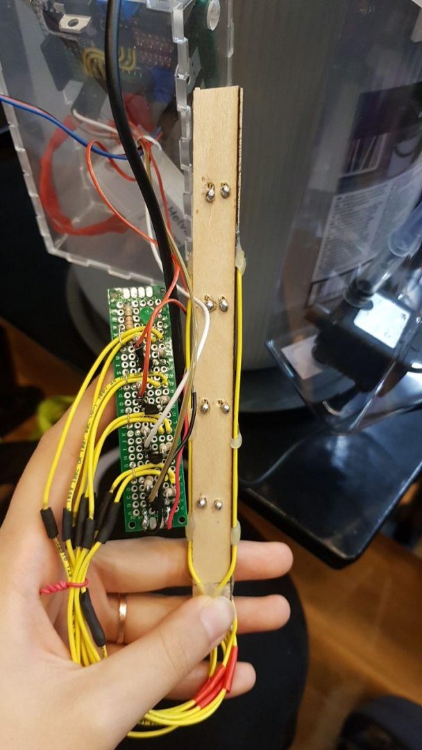
Self constructed water level sensor:
2. Hook
There are hooks attached onto the tank and holder in order for them to hang from the side of the pot that holds the plant. They are 3-D modelled using FreeCAD software.
3. Holder
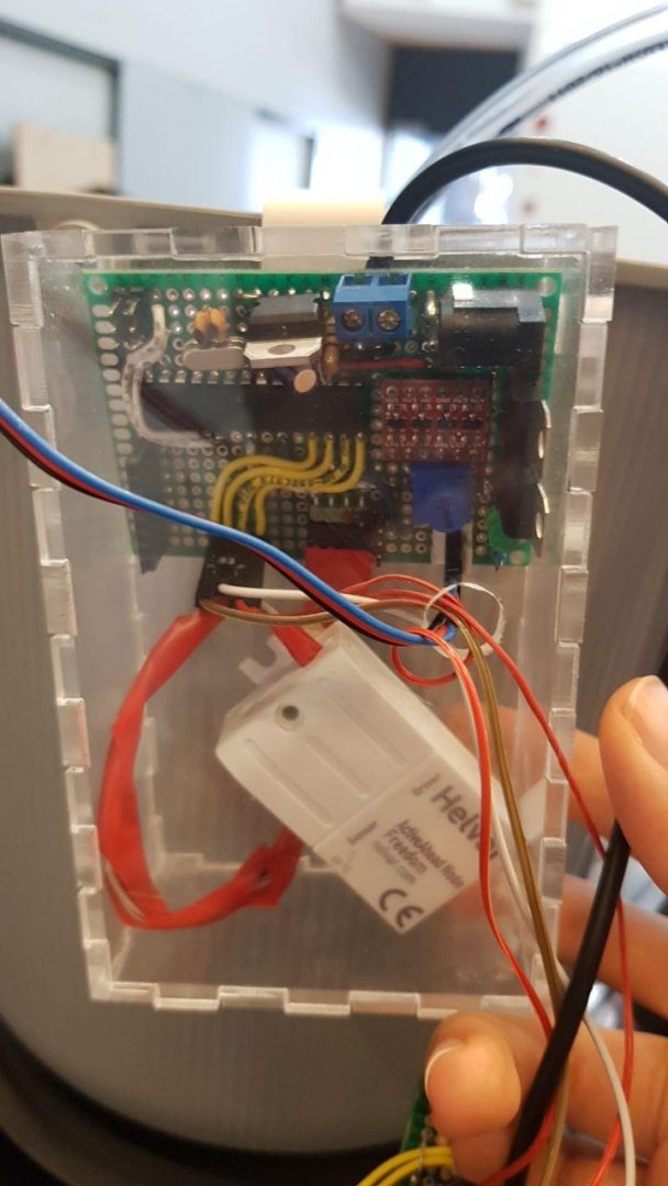
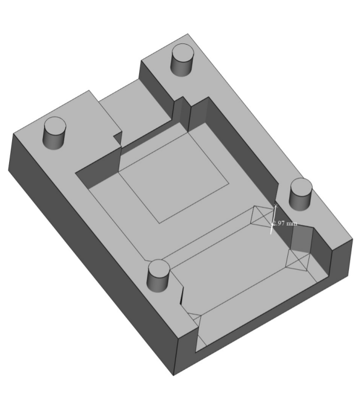
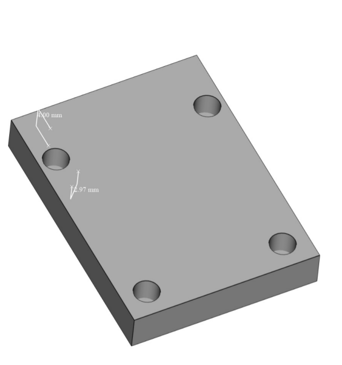
The holder is a 3-D modelled basic rectangular box made of acrylic glass that holds the board, LED, BLE-to-serial converter, power supply, and a wire holding the moisture sensor which comes out from the top of the box. The power supply, moisture sensor, and water level sensor wires go through holes drilled on the box.
4. Hose
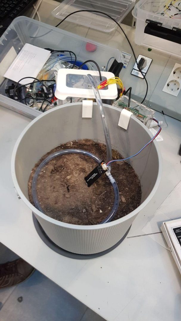
The hose comes out of the lid of the tank and goes around the pot. From the top view, it looks round. This is so that when the water pumps out of the tank into the hose, it will distribute the water evenly through the soil. The hose will have tight holes from under. The radius of the hose is 7 mm and length is chosen by the user according to their pot size. For now, we are using a 50 cm for the prototype.
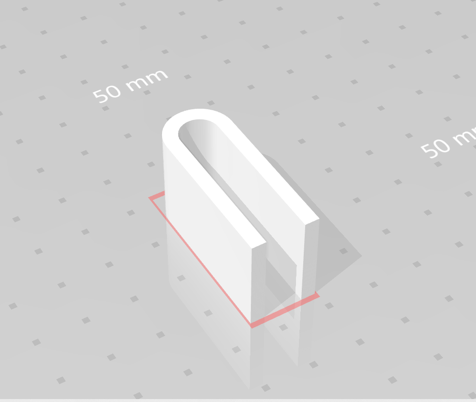
5. Soil moisture sensor
The soil moisture sensor is connected to the board which is in the holder and can be adjusted by the user to be placed wherever they like. It has a waterproof 3-D printed coating designed on FreeCAD to prevent it from damage by water.
The protocol
The protocol is implemented using Helvar’s protocol which is in turn based on the BLE mesh protocol. Helvar’s protocol uses 10-byte packets of which 4 are reserved which leaves 6 bytes to be used for the plant unit to use. The physical layer of the protocol is also not reliable which means that packets may be lost, which is something that should be taken into account. Taking the above mentioned restrictions into account the format of the packets to and from the plant unit is made to be as simple as possible.
1. Packet format
The ble-to-serial converter used in the project takes care of error detection and delivers discrete 10 bytes sized packets. It does not however guarantee that packets reach their destination, although a packet is guaranteed to be sent without errors. The format of the packet was thus decided to be simple, both to implement and to minimize the need for extra fields which would be needed for reliable transmission.
The format of the 10-byte packets is the following:
0 1 2 3 4 5 6 7 8 9
|reserved|reserved|reserved|reserved| src_id | dest_id | flags |register|data_low|data_high|
A field between “|” represents a byte of the packet.
The fields are received from left to right (0 to 9)
The first 4 bytes are reserved, they are always set to the bytes 0xfe 0x00 0x00 0x00.
The fields src_id and dest_id stand for the address of the source and destination nodes
respectively.
Flags is a bit field currently holding the following:
- bit 0, Error bit, set when if an error has occurred
- bit 1, Response bit, set when the packet is a response from slave to master
- bit 2, Operation type, 0: read, 1: write (only set when master sends to slave)
The rest of the bits are not used
The idea in the protocol is that values in the plant unit are abstracted as “registers”. loosely inspired by the I2C protocol. It is a master-slave protocol, in which the plant unit acts as the slave which receives packets and sends responses. The master can control or query the status of the unit by reading or writing the appropriate register address. As an example the desired water level for the plant would be represented by a register number and to set the water level the master would need to send a packet writing some value to that register.
Two byte fields are allocated for data transmission. The data could have a length of 8 bits,
16 or 32 bits (split into two different registers). The format of the data is dependent upon the register being used.
2. Communication using the protocol
The plant can be thought of as the slave device in a master-slave protocol. There are two kinds of operations, read and write. The master can read a register to query the current state or settings of the plant unit, or send a write packet in order to change the value in that register. All registers are readable but not also writable. Those registers that are read-only hold values for which it makes no sense for them to be also writable, e.g. the current water level in the tank cannot be written to (in contrast with the wanted moisture level register which it makes sense to write to). The slave will respond to both read and write packets with the value of the register, or with an error if the register is read-only or it does not exist.
The master is the only one responsible for ensuring that a read or write operation is carried through. If the master does not receive a response for its request within some time interval, it resends the same request and it repeats until it receives a response. The plant does not thus need to keep track of time or connection state. The master should only operate on one register at a time in order to ensure that the unit is in the state it is expected to be before issuing a new command.
3. Hardware
The basic components of the system are the following:
- AtMega328p microcontroller
- capacitive soil moisture sensor
- water pump
- ble-to-serial

Software
Code
The code for the project is divided into two parts:
- the code for the microcontroller inside the plant unit
- the code for the user interface
1. MCU code
The code inside the microcontroller handles the monitoring of the moisture level sensor, basic timekeeping, water tank level tracking and decision making. The microcontroller in use is the ATmega328p which is quite adequate for the application. The code for the mcu is written in C.
The moisture level samples are gathered asynchronously using the chip’s ADC and put in a ring buffer which is used as input to a very basic low pass filter used to somewhat reduce the noise from the sensor and the analog to digital conversion process. When the control loop requests the moisture level, the most recent low passed value taken from the buffer. This increases the latency a little bit, but this does not cause a problem, as the value of the moisture level sensor changes quite slowly. The only to be taken into account is that the buffer needs to be filled at least one time before the low passed value can be considered valid.
The mcu also implements basic timekeeping by utilising one of the on-chip 8-bit timers. Timekeeping is needed to ensure that the water has time to be absorbed into the soil between watering the plant and querying the next moisture reading. The timer causes an interrupt when its value equals a specific configuration register which causes the timer to reset its value and an interrupt to be generated. By setting the compare register to an appropriate value an interval of 10msec between each interrupt, which is used to increment the timekeeping value. The msec interval is adequate for the application at hand as wait intervals are measured in minutes which does not require very precise time tracking. In order to avoid overflowing the counter variable, it needs to be reset whenever it is to be used.
The mcu also utilises the on-chip uart controller to communicate with the ble-to-serial converter. The uart fires an interrupt whenever it receives a new byte, which is put into a 10-byte receive buffer for the protocol packet. The ble-serial-converter sends the packets one at a time so there is no need to do more, other than gathering the bytes and setting a global variable to notify the application that a new packet has been received. When sending packets through the uart, it is done in blocking mode, as there does not seem to be a need to do otherwise. The packet from the converter is represented as a struct using gcc’s __attribute__((packed)) which allows the buffer to be simply casted into a packet.
The following is some pseudocode showing in an abstract way the control loop of the mcu application:
function init:
initilialize_hardware()
enable_interrupts()
delay(0.1 sec) // wait for adc to gather enough data
function loop:
timer.reset()
while 1:
if packet_received:
process_packet() // process packet and send response
else if timer.value() == settings.inspect_interval:
moisure_value = moisture.read()
should_water_plant(moisture_value)
water_plant()
timer.reset()
2. User Interface
The graphical user interface files were created using Pyqt, which was chosen because it is one of the most powerful and popular cross-platform GUI libraries.
Qt Designer was used to make ui files first, then those files were converted into python files to be connected to the code. The initial design was intended for mobile application, but the final GUI is for the use on desktops.
The user interface will be built on existing software, ActiveTune Computer at the company demo presentation day.
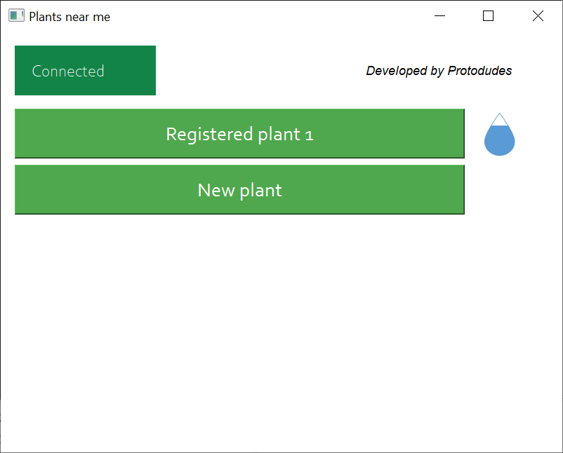
When the user opens up the application, it will send bluetooth signals to “ask” and get responses from nearby plant units. The plant units that responded will be displayed on the screen. If there is a new plant unit detected, then it will be indicated as new. The user can add information about the new plant and choose the watering options. The registered plant unit’s water tank level will be displayed in a droplet icon.
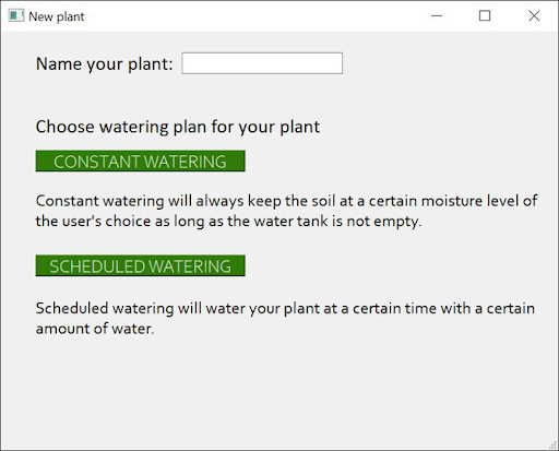
There are two options to choose when a new plant is added to the application. The user can add a name to the plant unit on this page.
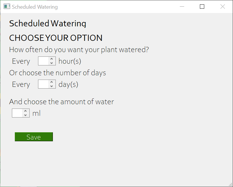
Scheduled watering option will ask the user to choose the watering schedule. The user has to choose the interval of watering and the amount of water that will be given to the plant each time.
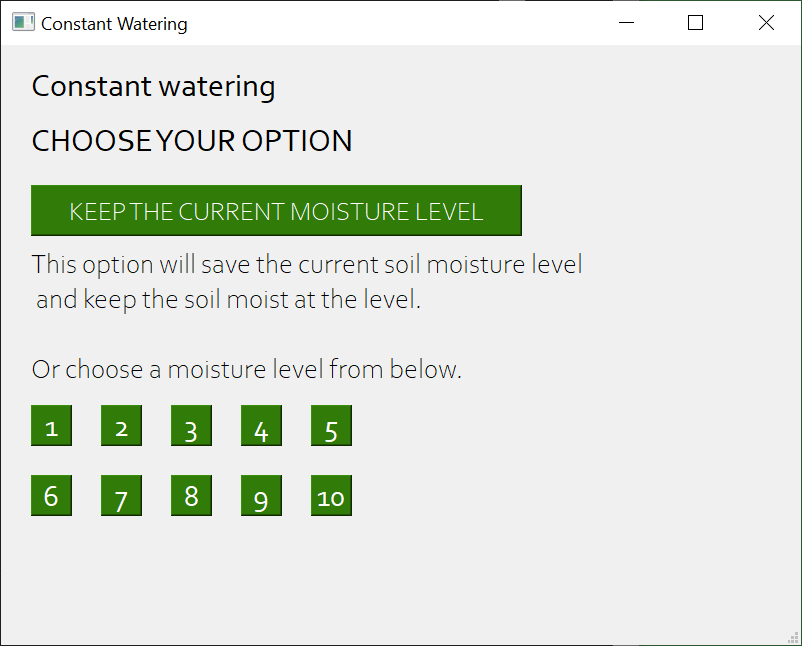
Constant watering will keep the soil at a certain moisture level of the user’s choice. For user’s easy understanding, the levels can be chosen from between low, medium and high. Pictogram that indicates information on each button will provide a list of plants that are suitable for each level of moisture. Keeping the current moisture level is also possible. The current moisture level will be saved and the soil will be kept moisturized so that it will always be at the saved level.
The user can consult the chart of optimal moisture level for each plant species, which can be found in the references page in the final report.
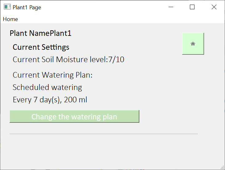
The information of each plant unit can be accessed from the main page. Individual plant unit information sections will inform the user of the current soil moisture level and watering plan. The notifications can be turned on or off for each plant unit in the homepage. If the notification is turned off, the user will not get any message that the water tank is empty. The watering plan can be changed from this page.
Moisture sensor sampling
Initially the moisture sensor used was the Funduino water moisture sensor. The sensor’s working principle is based on the fact that the resistance of the water is lower the more water there is in the soil. However this turned out not to be a good solution as the sensor was dependent on many factors such as temperature, position in the pot and the electric properties of the soil. Also the amount of salts contained in the water used for the watering could vary which would alter the resistivity of the soil, thus giving skewed results. Below is an example of the data received by the Funduino moisture sensor over the period of around 3 hours.
Although the error is not significantly big we decided that the sensor is not as reliable as we would like it to be, and for that reason we replaced it with a capacitive water level sensor.

Links
Github: https://github.com/KonstantinosKaratzidis/ActivePlant
Final report: https://docs.google.com/document/d/1ditGQ7lw0K3hRSwncUCeV0yFkWIIK4cFMeXSmN2GAmA/edit#
3-D models:
License
Source code: MIT-license
Models: Creative Commons (CC BY 4.0)