

This project is mainly designed for couples and people who are in a long-distance relationship. They can send and receive a touch for and from your loved ones.
The idea is that there will be two huggable teddy bears coupled together, and when one touches the back of the first bear, the hand movement is mirrored to the arm movement of the second bear. Alternatively, one can still send the touch using the touch screen of the mobile phone, if they are not carrying their bear with them. Simply think about your loved one, use the bear to send a touch, and the bear will caress your loved one.
The bear is mainly designed for couples and people who are in a long-distance relationship. They can send and receive a touch for and from your loved ones. The project includes two main parts: One back of a bear that can be caressed and a moving arm that mirrors the caressing motions. In a complete product, these would enable two users to have a real-time and a two-way connection.
Sensors
In this project we need sensors to capture and record the hand caressing on the teddy bear’s back. Determining the position of the hand, the direction of motion, and the speed of caressing are very essential requirements to create a precise imitation of the hand caressing on the bear’s arm. After a number of tests of various sensors we decided that the most suitable sensor which satisfy the previously mentioned requirements is the Force-Sensing Linear Potentiometer.
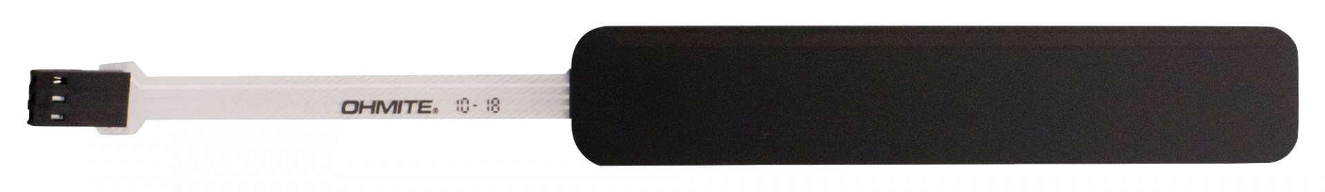
Force-Sensing Linear Potentiometer (FSLP)
Micro-Limit switch
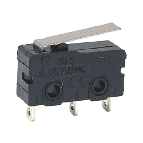
When the power is off, the information about the position of the Stepper Motor is lost and the motor cannot determine what the position is at next power up. So we had to use a simple limit switch that can be used to “Home” the Stepper Motor at startup, and initials its position. We can then calculate the maximum number of steps we can go forward from that position and use that as the limit travel the stepper can move. This way we don’t have to use another Limit switch on the other end of the arm.
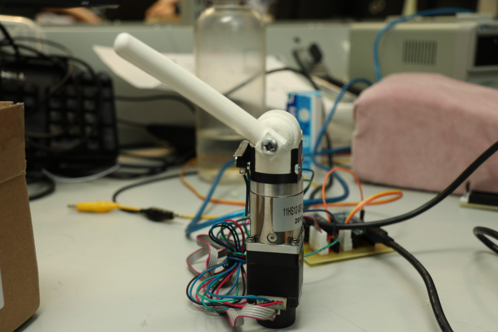
Motor
For our project we chose Nema 11 Closed-loop Geared Stepper motor with a gear ratio of 27:1. This is the smallest stepper that has enough torque for our purpose. This stepper used with the TMC2208 driver is silent and can be turned by hand if it gets stuck.
The motor is rated for a torque of 0.07 Nm, which with the gearbox is 1.5Nm (~15Kg/cm) As described in later chapters, we built a bevel gearbox to turn our shaft which lessens the efficiency of our system, and as such lessens the torque. We measured a torque of (check the actual torque) in our final setup.
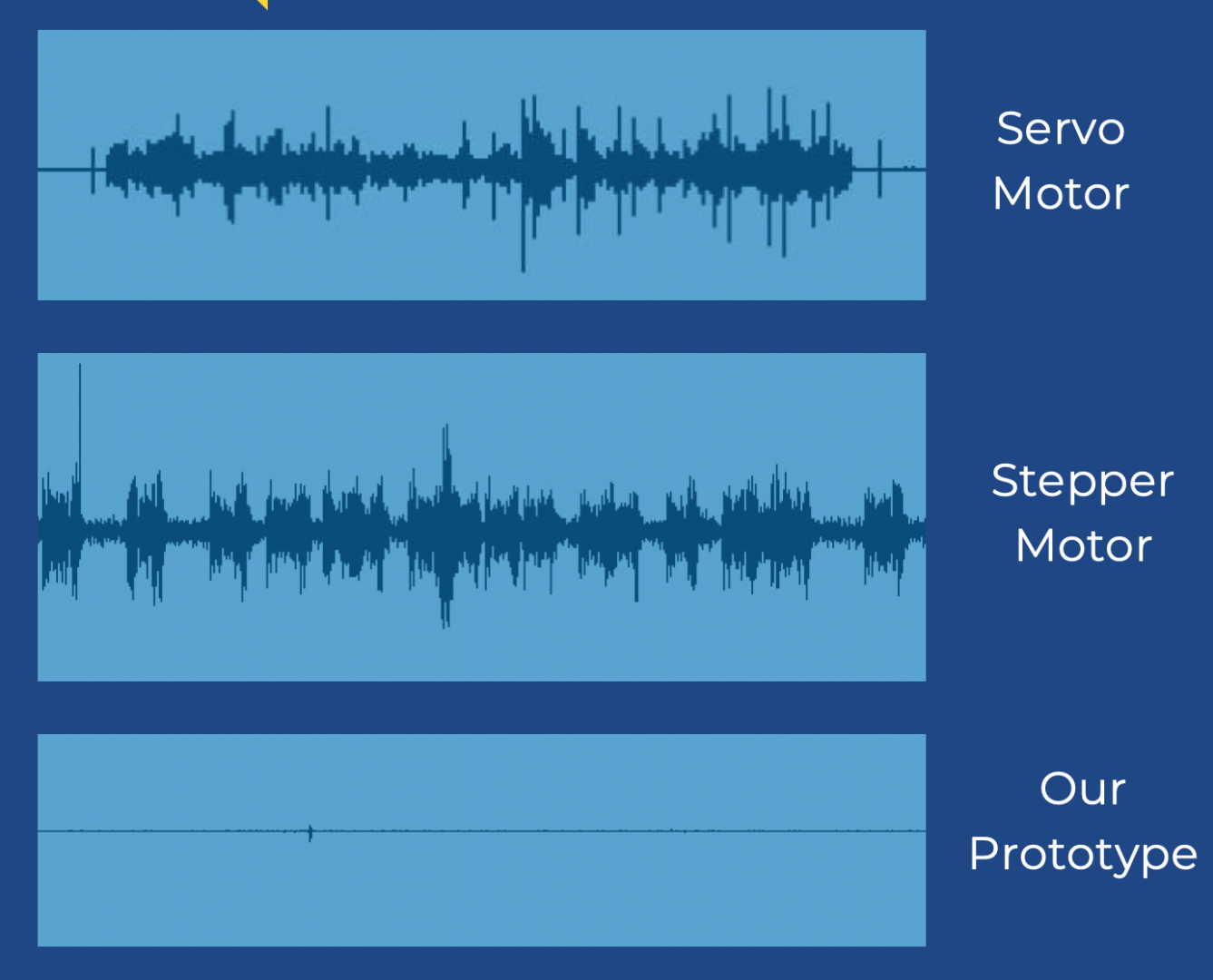
Noise comparison of the prototype motors
- Noise of Motors:
Different motors were compared for their noise waveforms and it can be concluded from the figure that we were able to achieve a very low noise or almost no noise level for our prototype.
Encoder
In our prototype we use an optical incremental encoder that came with the stepper motor. We collect the data from incremental encoder and process it into a position. An easier option would be to get absolute encoder separately and use that instead.
Mechanics
As we changed 3D printed gears to metal ones we needed to make a new box fitting for them. The new box is a lot smaller and has less extra space. Also the closing system was changed to two 2.5 mm bolts on the bottom part of the box. Also ball bearing that is attached to the gear going to the arm is supported only on one side of the wall and isn’t fitted between walls. As the ball bearing was a bit wobbly without support from all sides we put a small amount of super glue between the bearing and the wall.
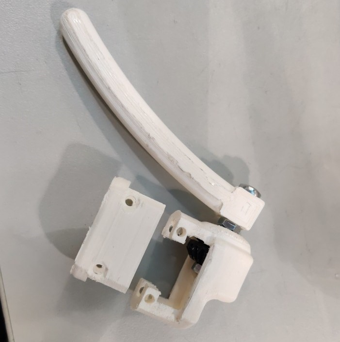
Final version of the gearbox
Circuit
The Circuit assembly consists of two systems, once is the Transmitting end which sends the direction of the motion as well as the position the motor has to move. The other part of the system is the receiving end which receives the values and moves the motor accordingly.
The Transmitter Circuit
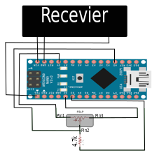
Circuit Diagram of the Transmitter
The transmitter circuit consists of the FSP sensor, with a resistance of 4.7K ohm as shown in. The Transmitter pin of the arduino is connected to the receiver pin of the receiving end. The arduino is powered by the 5V output of the receiver end, a 200uF .
The Receiver Circuit
The Receiver circuit consists of the Micro Limiting switch, Silent Stepper motor driver (TMC2100), encoder(HKT2204) , stepper motor (NEMA11),Arduino Nano as shown in figure 16.
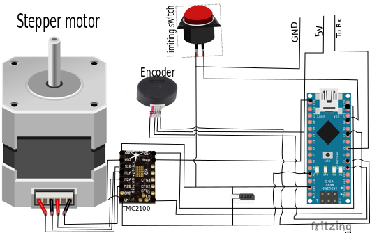
Circuit Diagram of the Receiver
The touch Logic
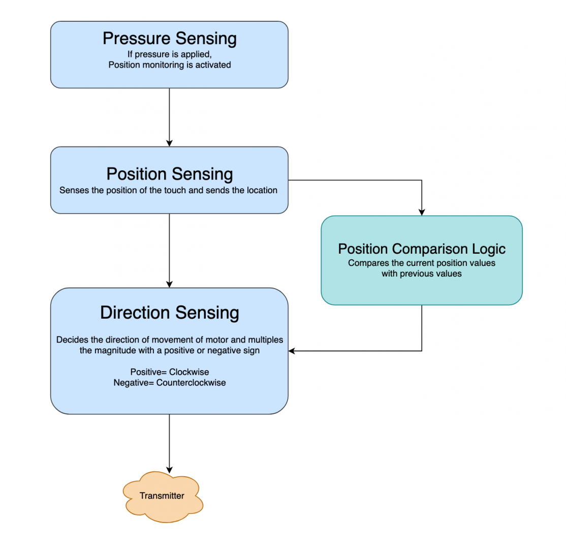
Flowchart for the Transmitter logic
The motion Logic
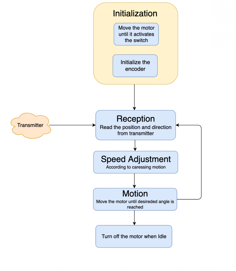 Flowchart for the Receiver logic
Integration of the final version
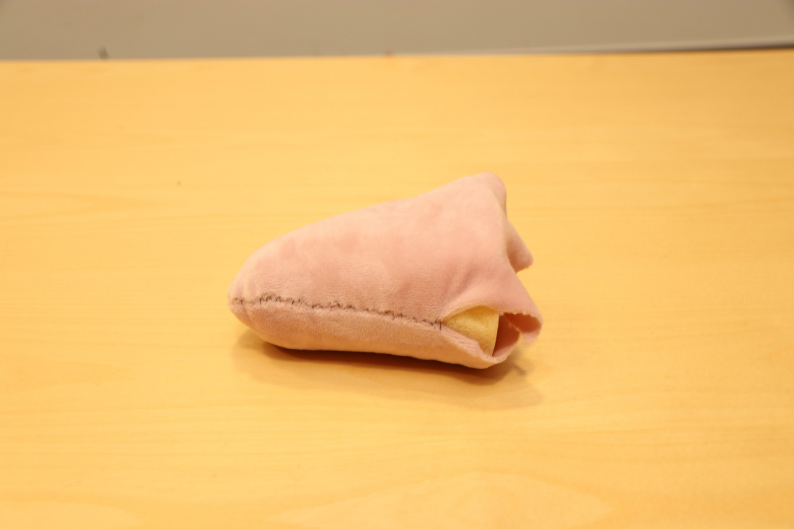
As none of the students were studying design the objective was to make the end result a memory foam back with the sensor on soft surface and under a fabric layer and a caressing paw. The back and paw was connected with a wire and all PCBs were inside boxes so the prototype was userfriendy. All sewing and cutting was done by hand.
Back of the bear

The Arm
The bear’s arm design
The Hardware
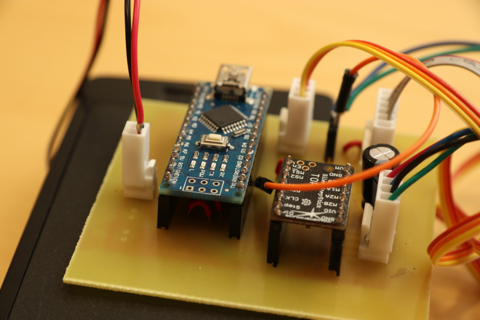
The final PCB with assembled devices
Assembly
When the PCB, sensors inside the back, motors, the arm were finished, the final version was assembled, the transmitter was put inside a laser cut box as shown in the figure below
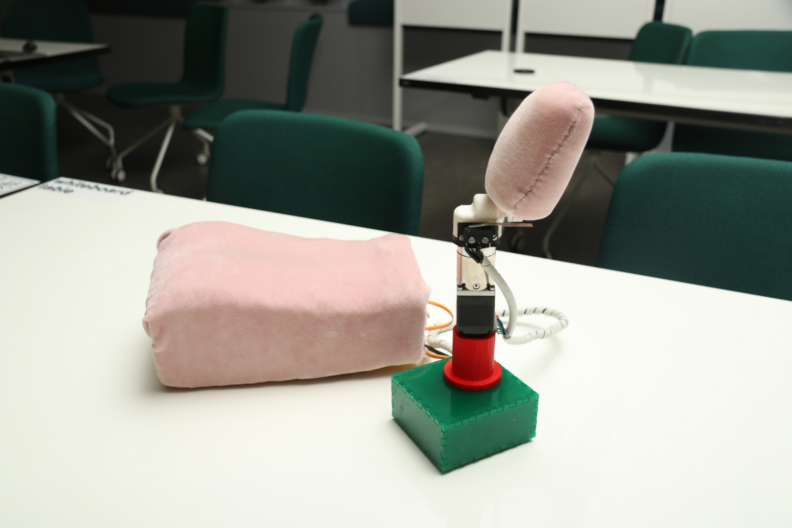
The final Assembled Prototype
Links
- Final Report
- CAD Designs
- PCB Design Files
- Arduino Code
- Project plan
- Demo day Presentation
- Presentation poster
License:

This work is licensed under a Creative Commons Attribution 4.0 International License.
Code License: MIT Licenced software