
Sensor Testing Rig
Helvar wants to do research on various sensors for sensing humans. For this research they need to conduct some tests on their prototype sensors. Typically these tests could be run in typical use environment such as conference rooms. For increased effectiveness these tests need to be be run in a testing environment, that provides ability for test automation as well as repeatability. To reduce the costs and logistical problems caused by such testing environment it should also be miniaturized. Because Helvar doesn’t have the time to build the rig themselves, they asked our student team (Aalto University, Protopaja-course) to do it.
Helvar is planning on testing FIR and PIR sensors, cameras and radars with the rig. Because the sensors are supposed to recognize a person in a room, the rig must have something to simulate people. This is done by building objects that have a moving aluminum “head” that can also be heated. Also the location and sensing angle of the sensor is very important, therefore the sensors must have the ability to be moved and tilted above the objects.
Testing rig must also be easily controllable with a computer to make sensor testing efficient and easily automated.
System Overview
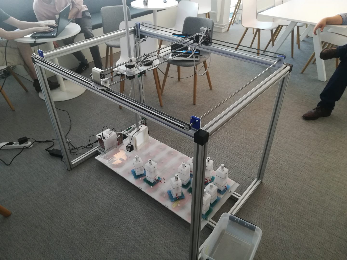
The system has two main functions, the first is to provide the ability to move the sensor being tested around the testing space, and the second is to simulate humans for the sensor to detect. The system consists of a frame, on top of said frame, a base plate providing the mounting positions for testing units at the bottom of the frame and testing units that provide the movement and heat to simulate humans. The testing units can be set to different positions on the base plate. The mounting holes have magnetic connectors to make configuring the testing positions easy. The different parts of the system are controlled with an Arduino Mega board.
The frame
The frame is constructed out of 40*40mm i-type aluminium profile and its outside dimensions are 1280*880*940mm. Aluminium profile was chosen for the system because it is easy to assemble thanks to the different connector parts available in these systems, and it allows easy mounting of parts of our own design.
Motion system
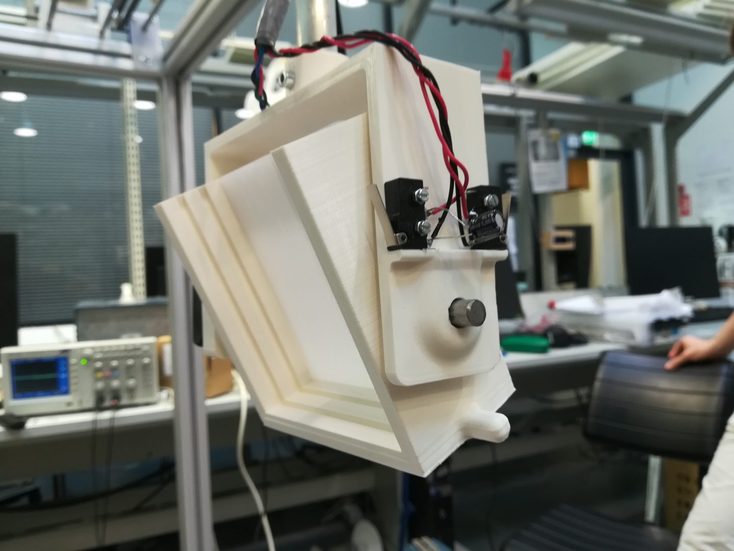
The system for moving the sensor around the testing space is located on top of the frame. The system provides control for horizontal movement and sensor pitch. Additionally the system provides options to set up the system with different sensor height and yaw.
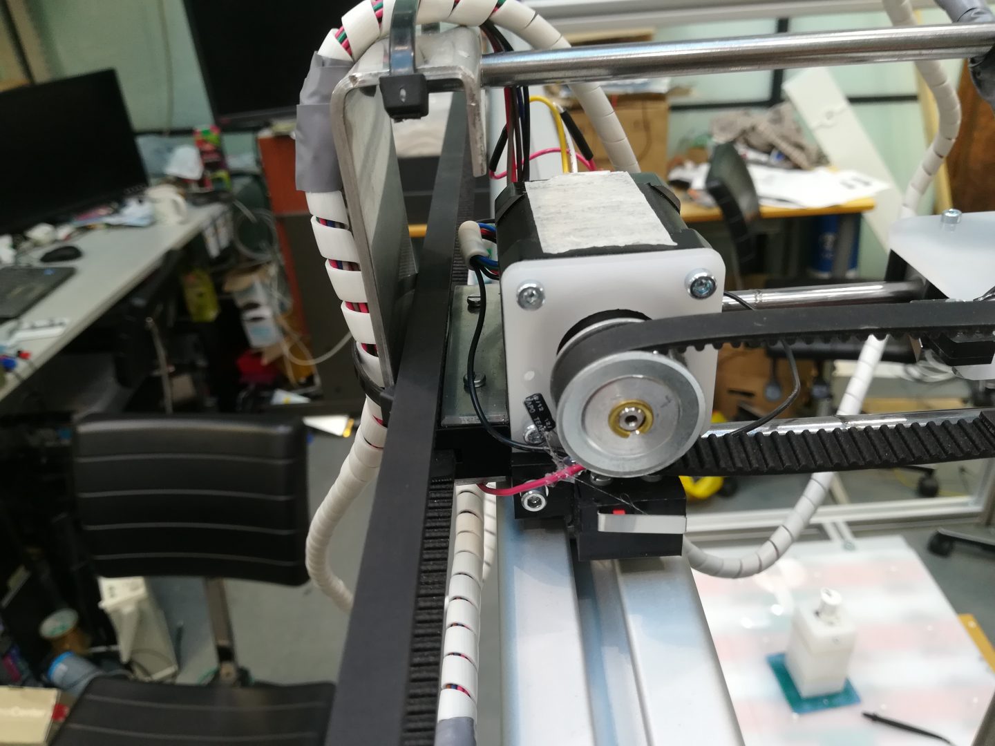
A stepper motor is used to drive a belt drive to provide movement along sliders in the grooves on top of the frame’s aluminium profiles to provide the first axis of horizontal movement. Drive is sent to both sides to keep the both ends of the second set of rails in the same position along the first axis of movement.
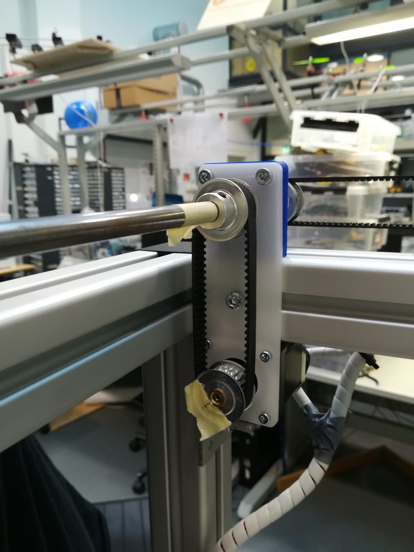
The second axis of horizontal movement is similarly driven by a stepper motor. The movement occurs on rails suspended between two sliders on opposite sides of the frame. An additional third rail was added to provide extra stiffness.
Sensor height and yaw can be set manually using a locking mechanism on top of the slider moving on top of the testing space along the second set of rails.
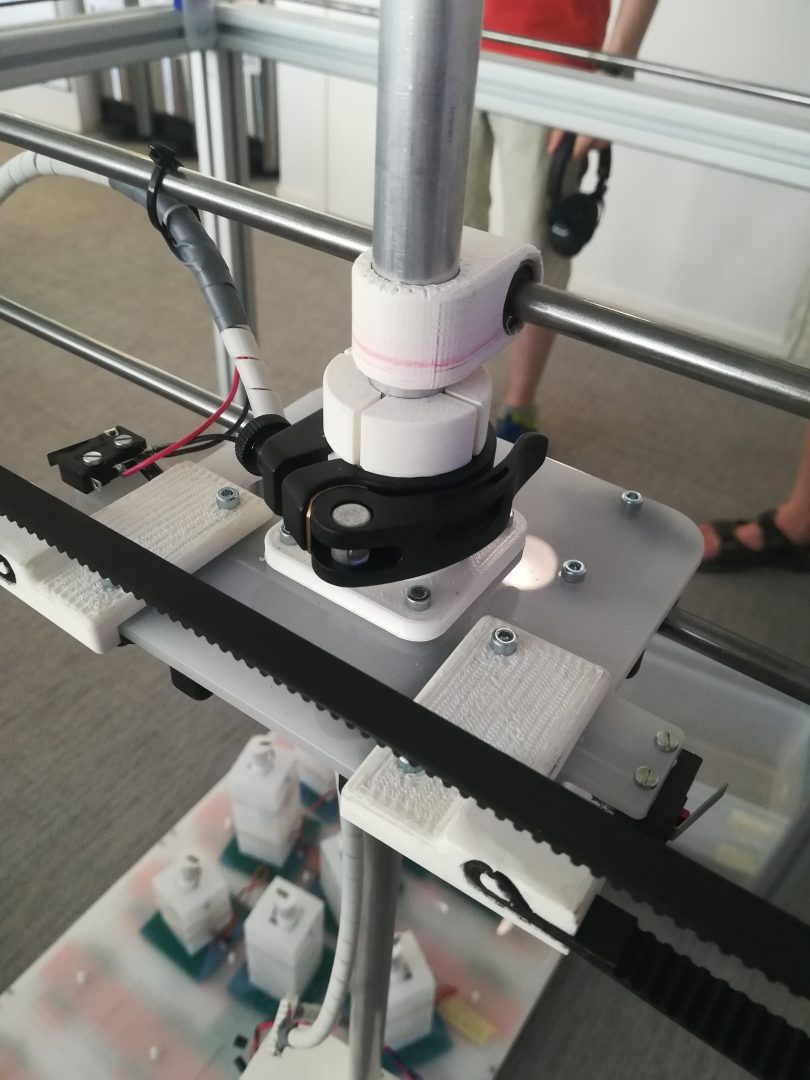
Sensor pitch is controlled with another stepper motor at the sensor head. Limit switches provide support for homing functionality to all stepper motors in the movement system. Sensor mount is a 10*10*3mm piece of acrylic that can be easily changed to provide adaptability for different types of prototype sensor housings.
Testing objects
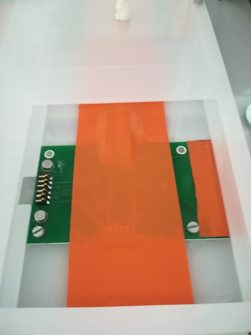
The purpose for the testing objects was to simulate humans for the sensors that are tested. In this case it means they need to be able to produce movement and provide a temperature similar to a human head. Testing objects consist of base, body and head. Base provides connection for power (5 V and 12 V), ground and servo signal. It also provides steady platform for the body and capability to turn the body 90 degrees around the vertical axis. Base was made of two 3 mm acrylic plates and one 0.6 mm PCB that were glued together. The base also includes magnets for the magnetic connectors and reed switches of the base plate mounting positions.
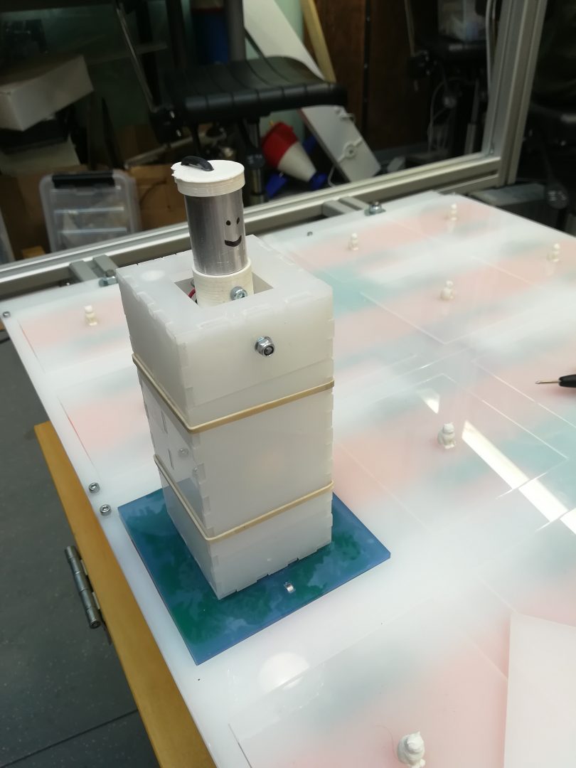
Body was made of 3 mm acrylic, with a laser cutter. Body provides mounting places for a servo (K-Power P0900) and axis (3 mm threaded rod) to which the head was attached to. Then bodies of 5 different heights were made to simulate persons of different heights.
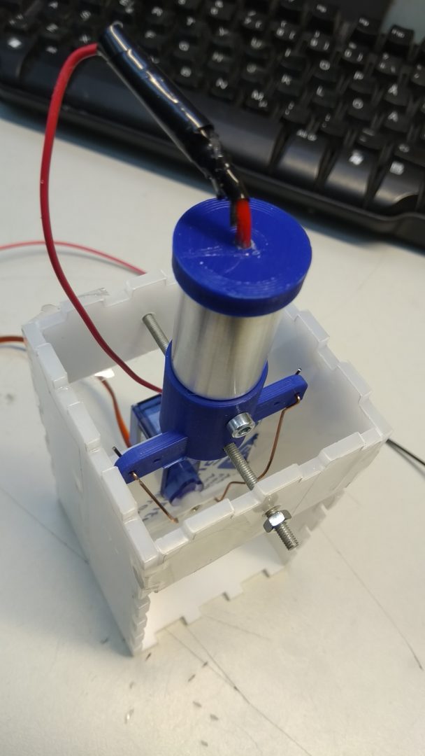
The heads were machined from aluminium rod. Upper part of the head was drilled hollow for the heating resistor to fit in. The resistance of the resistor was 33 ohm. Thermal grease was used to improve the heat transfer from resistor to the head. Aluminium head was mounted on a 3D printed holder that attaches the head to servo (via steel wire) and 3 mm axis.
Testing unit matrix
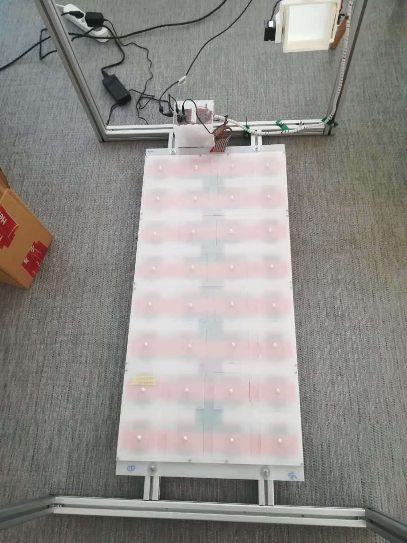
Testing units can be mounted in any of 32 slots in a base plate at the bottom of the device. the slots are arranged in a 4 by 8 grid. The mounting slots contain magnetic connectors to make reconfiguration of testing setup easy. The connectors provide current and the control signals required to control testing unit behavior. The slot also contain reed switches that are activated by a magnet in the base of the testing units to improve safety of the system. When not in use, the slots can be covered with a cover plate with a stylish cat shaped handle.
Software
The code was written in C++ and runs on an Arduino Mega 2560. As the main xy-plane motion steppers required a serial line to operate, the main software challenge was handling simultaneous communication between the user, the Arduino and the two stepper motors efficiently. The end result was a light weight polling loop that iterated over the different communication channels and command execution functions. The high level software architecture is shown in the diagram below:
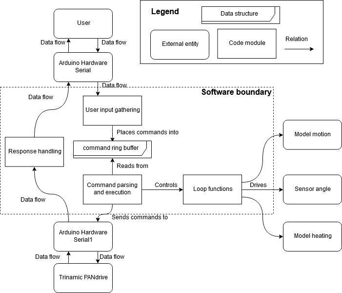
The user input is gathered every loop, and if a command is detected it is placed into the ring buffer. Commands are then parsed and either sent to the stepper drivers or used to control the various model and sensor loop functions. The responses from the stepper motors are handled and then displayed back to the user. The code provides feedback on executed functions and improper input parameters and is designed for safe operation.
Team
Johannes Lunkka
Tuomas Julin
Samuel Laine
Ville Hiltunen
Files
Project plan
Final report
Github
Licences
Code: MIT Licenced software

This work is licensed under a Creative Commons Attribution 4.0 International License.