
![]()
Energy Harvesting Bluetooth Low Energy Beacon

Introduction
A Bluetooth beacon is a device that broadcasts a signal to surrounding devices. A common issue with these devices is they are often battery-powered, requiring service every couple years. The aim is to find a solution to this issue by powering the device in other ways. We are trying to achieve this using the thermoelectric effect. Using a thermoelectric generator, or TEG for short, we can harvest waste energy from a hot metal surface. The voltage generated depends on the difference in temperature between the two sides. We want to assess the viability of using TEGs as energy harvesters for Bluetooth beacons. In addition to this, a part of our challenge is to find a way to mount our device to a LED-driver provided to us.
Overview
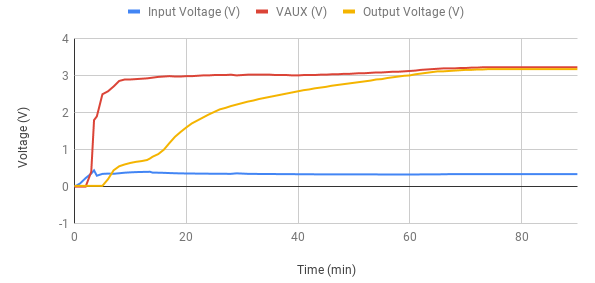
We didn’t have a proper testbed for the LED-driver at first and thus we started with simulating it with resistors. Based on the data we had from thermal images the hotspots on the LED-driver would have a temperature of about 80°C, which led us to design our first version based on that assumption. We were then generously given a testbed simulating a set of dimmed lights with a hot side temperature of around 50°C. In combination with the shortcomings of our heatsink it forced us to do a complete redesign of the circuit. In the end we found that the lowest temperature at which our circuit works is about 70°C. The graph below shows how the output voltage of the circuit behaves over a period of 90 minutes. For reference, our Bluetooth device needs a minimum of 1.7V to power up. For more details check out the full report at the bottom of the page.
Printed Circuit Board
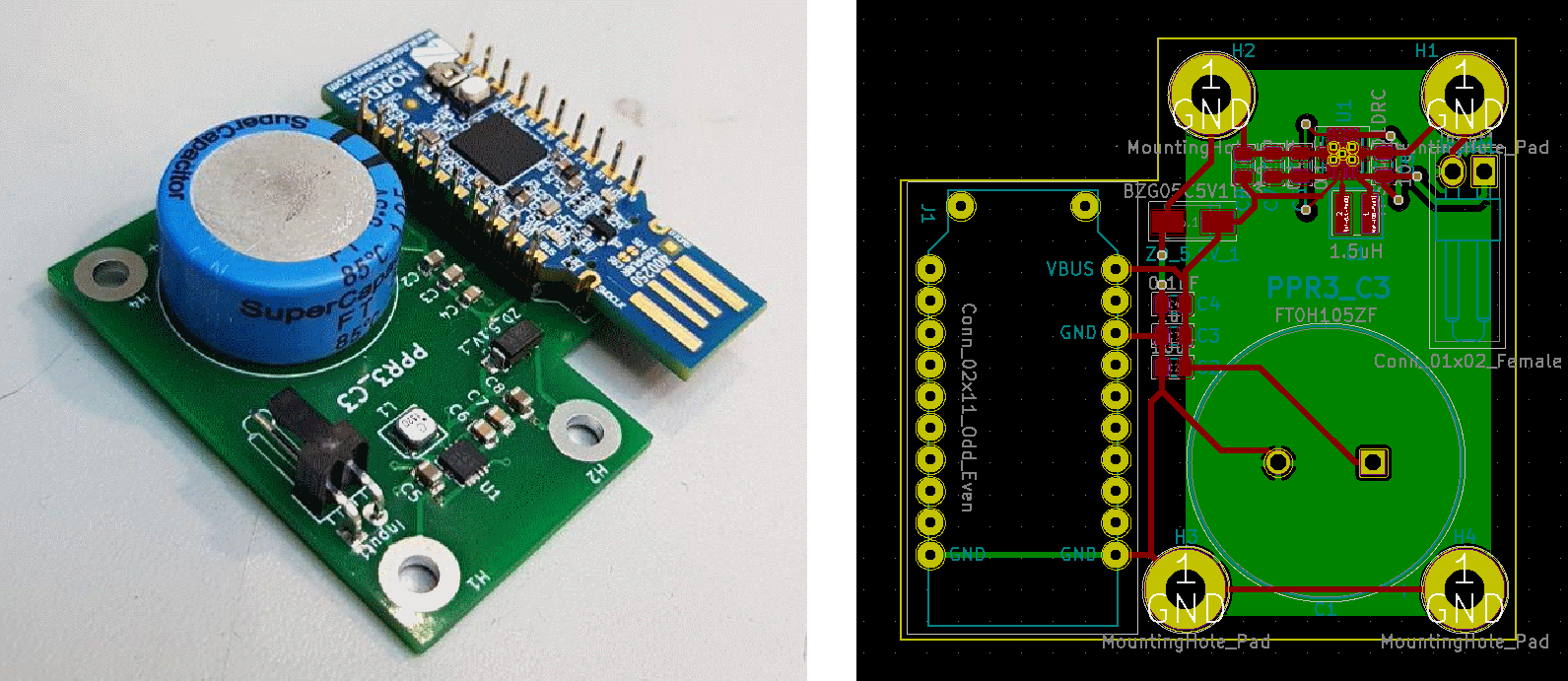
Our circuit had a very simple task, to boost up the voltage and store energy in a capacitor. Importantly doing so reliably and providing a secure connection between the circuit and our Bluetooth device. The task at hand allowed for a very simple design. Our first two revisions having an entirely different converter the PCB went through some noticeable changes throughout the process. At first, we went with the R-78S as our converter. With its 0.65V input voltage, it suited us with the data we had at the time, but the test setup with a smaller load forced us to adapt to a lower temperature. Since the scenario changed mid-way we were forced to revamp the design completely and go with a TPS61201 boost converter. The lower minimum input voltage at 0.3 would allow us to run the circuit at a steady state. The startup voltage of 0.5V was also low enough for a start-up from room temperature to get the converter running. In the third and final revision, we opted for a pin row to keep the Bluetooth device in place. We also added a cutout allowing the user to potentially edit the software on the device. The software used to design our PCB was KiCad, which is open source.
Hardware 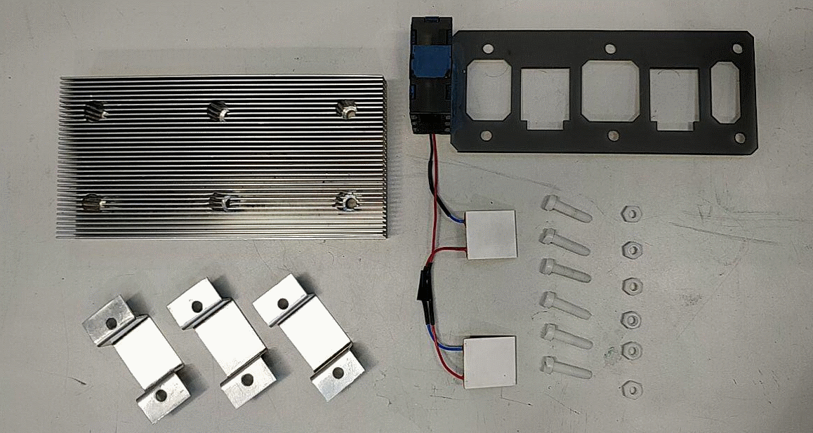
For the hardware design, we went with the most simple and functional solution possible. Three metal plates which generate a downwards pressure onto the LED-driver, sandwiching the generators in between the heatsink and the heat source. To aid in keeping the TEGs in place and prevent sliding we laser cut a plastic board that simultaneously worked as a base for the box containing the circuitry.
Software
In the project we used Nordic Semiconductor’s nRF5_SDK_15.3.0_59ac345 SDK. The example ble_app_template was configured to work with the pca10059 board that we used according to the tutorials shown below. This allowed us to test whether the beacon is powered up when we connect with a smartphone. On the smartphone we used the nRF Connect application designed to enable the connection and configure BLE beacons.
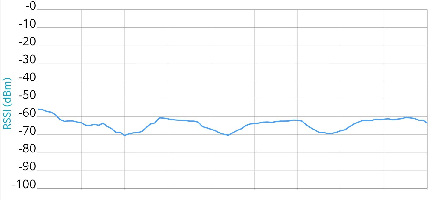
In our case, the nRF Connect app was used. It allows us to scan and map an RSSI graph of the connection to detect any discontinuities in the connection, which is perfect for monitoring whether the beacon is receiving enough power. The software environment used in the project was SEGGER Embedded Studio for ARM 4.18 on Linux. Other necessary software
is listed below:
-GNU toolchain for ARM
-GNU Make 3.81
-nRF5 SDK 12.1.0
-nrfjprog
-nRF Connect application
Tutorials used in setting everything up are:
- “nRF52840 Dongle Programming Tutorial,” by Einar Thorsrud
- “Starting Development with Nordic nRF5X and GCC on Linux (Part 1),” by gustavovelascoh
- “Prototyping BLE apps on the nRF52840 USB Dongle (Part A),” by Mohammad Afaneh.
Conclusion
We are able to get our device to work with a temperature of around 70°C, making the device like this viable. Out of our two TEGs, we are able to harvest 20-25mW of power. With a more suitable heatsink, we would most likely be able to harvest even more, or reduce the number of TEGs down to one and save space and costs. Other than what we have achieved materially, we have learned a lot about project management, circuit design and other aspects during the project. We hope that what we have done could be developed further, improving on the shortcomings, and maybe make something commercially viable.
Group Members
Resources
File Downloads:
Licenses:
Code: MIT Licensed Software

This work is licensed under a Creative Commons Attribution 4.0 International License.