
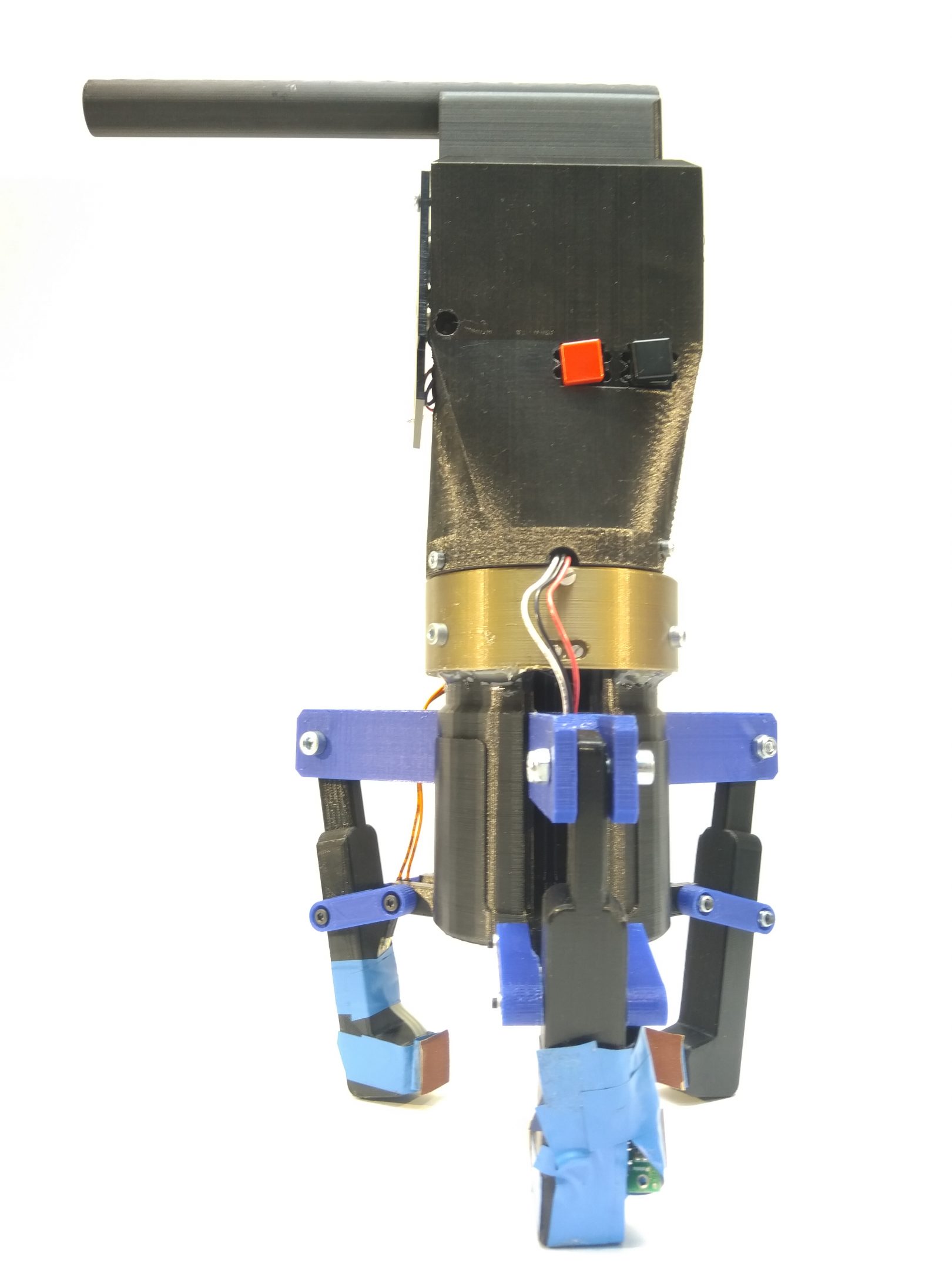
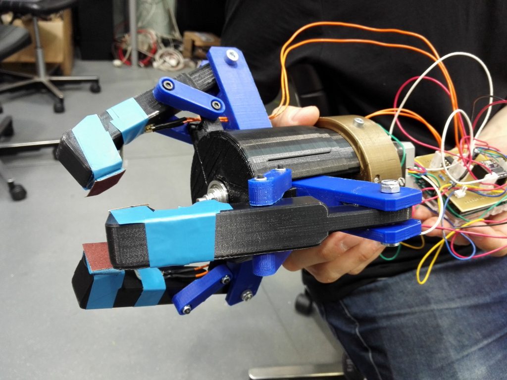
Piston-Hand
Information and instructions for the piston hand created during the course.
General information
Our Project for Futurice
The expected outcomes of this project are to create a software and hardware that equip a robotic limb with precise enough haptic feedback loop so that it is capable of handling delicate objects without breaking them. The feedback loop is constructed from two major parts: (1) a hardware and software which adjust the force applied to objects, and (2) a virtual twin of the robotic hand which can be used to simulate and monitor the robotic limb movements.
Main use cases for this would be humanoid robots which interact with humans, such as simple greeters at a store. Considering how strong a force even simple servos can create, it is important for any robot that interacts with humans to have a sensing system installed in order to avoid painful accidents. Some more complex use cases are applicable from a future perspective. For example, cooking robots should be able to handle fragile materials such as egg or glass. Our goal is to create a robotic hand that can exert enough force to break an egg, and then implement a precise enough feedback system that it can gently grab and hold an egg without damaging it.
Functionality
The robot hand functions through several steps. Once started, the robot will calibrate itself to a maximum opening position where an endstop button is located. Then, it moved to an offset position where it is ready to grasp any objects.
After the calibration, the robot will attempt to grasp an object, if such is detected by an infrared proximity sensor. The robot will close it fingers for grasping and stop applying more strength after the pressure threshold, which is measured by a pressure sensor, has been reached. At this point, the robot will hold onto the grabbed object until it receives another command from a button on the wrist.
The command can be releasing or destroying. If receiving a releasing command, the robot will open the claw completely and then wait for another object. On the other case, it will apply more force to the object as it can.
Files
CODE: futurice-piston-hand
All hand files in one package (.zip)
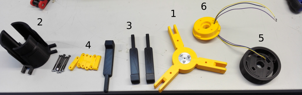
Robot parts
Parts for the robot hand
-
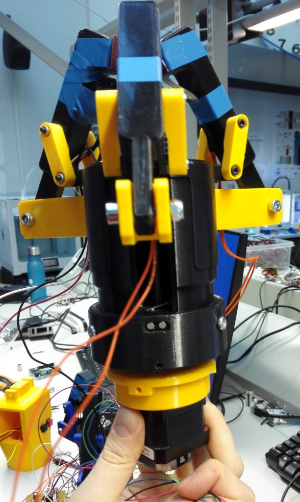
- 3D printed parts:
- 1 piston (1)
- 1 enclosure (2)
- 3 fingers (3)
- 6 finger middle pieces (4)
- 1 wrist part
- 1 wrist cover
- 1 hat (5)
- 1 motor attachment (6)
- 1 handle (optional).
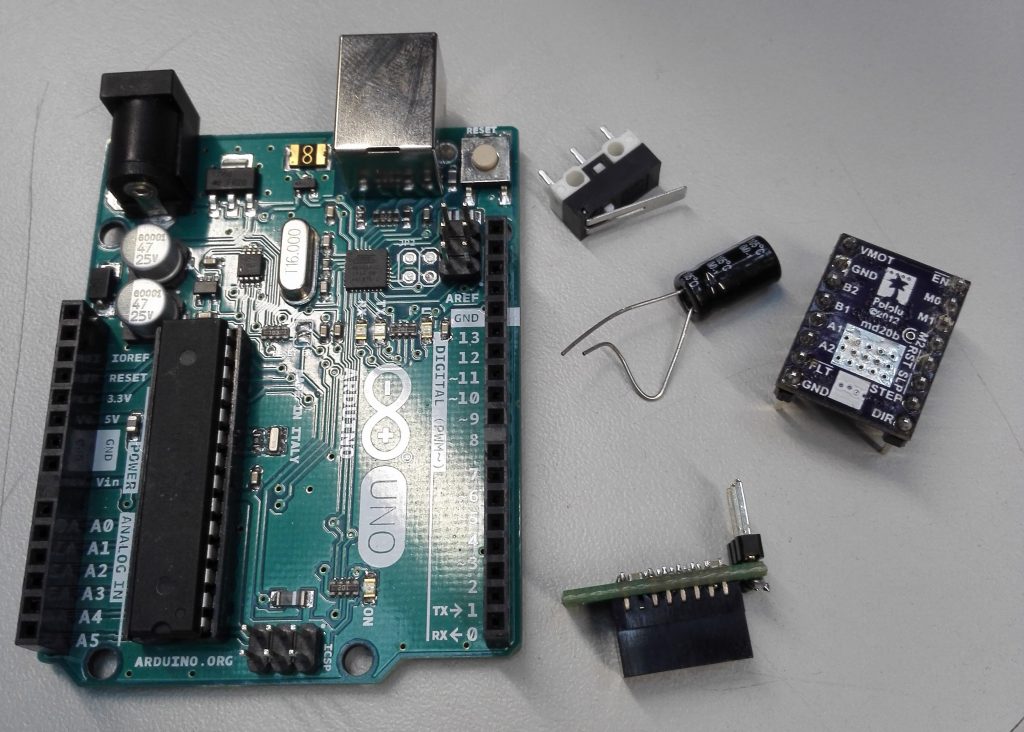
- 1 Arduino Uno or a similar control board.
- 2 pressure sensors FRS402.
- 1 infrared sensor or another proximity sensor (We used Pololu GP2Y0D805Z0F).
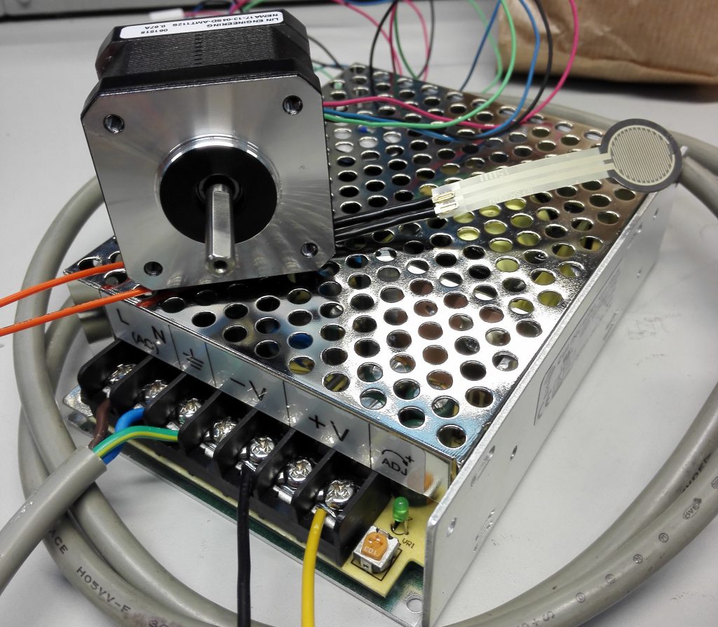
- 1 stepper motor to spin the threaded rod (We used Mercury Motor SM-42BYG011-25 for one prototype and NEMA17-13-04 SD-amt112s for the other).
- 1 stepper motor controller for controlling the motor (We used pololu DRV8255 stepper motor driver). Make sure it can handle the voltage your motor requires. The wires of the motor should be connected in proper polar order. When the directional pin is false, the motor opens the hand. When the pin is true, the motor closes the hand.
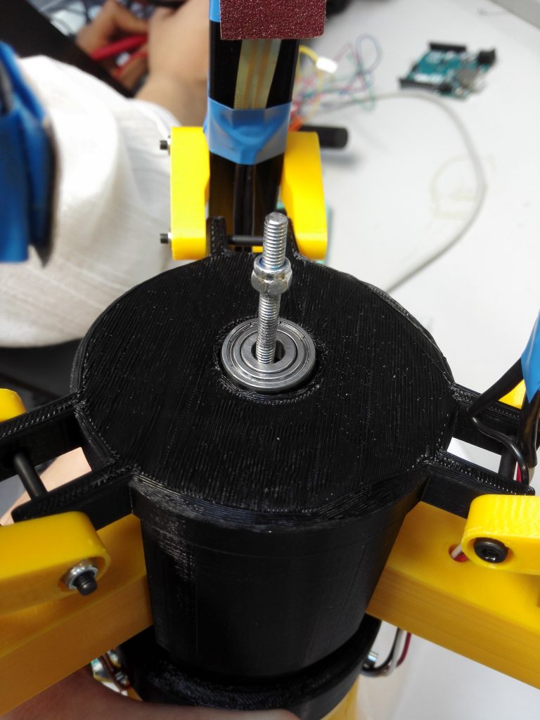
- 1 threaded rod, at least 15 cm long (We used an M4 thread rod which is suitable for our design, another rod can be considered but required modification in the 3D printed parts).
- 1 endstop switch.
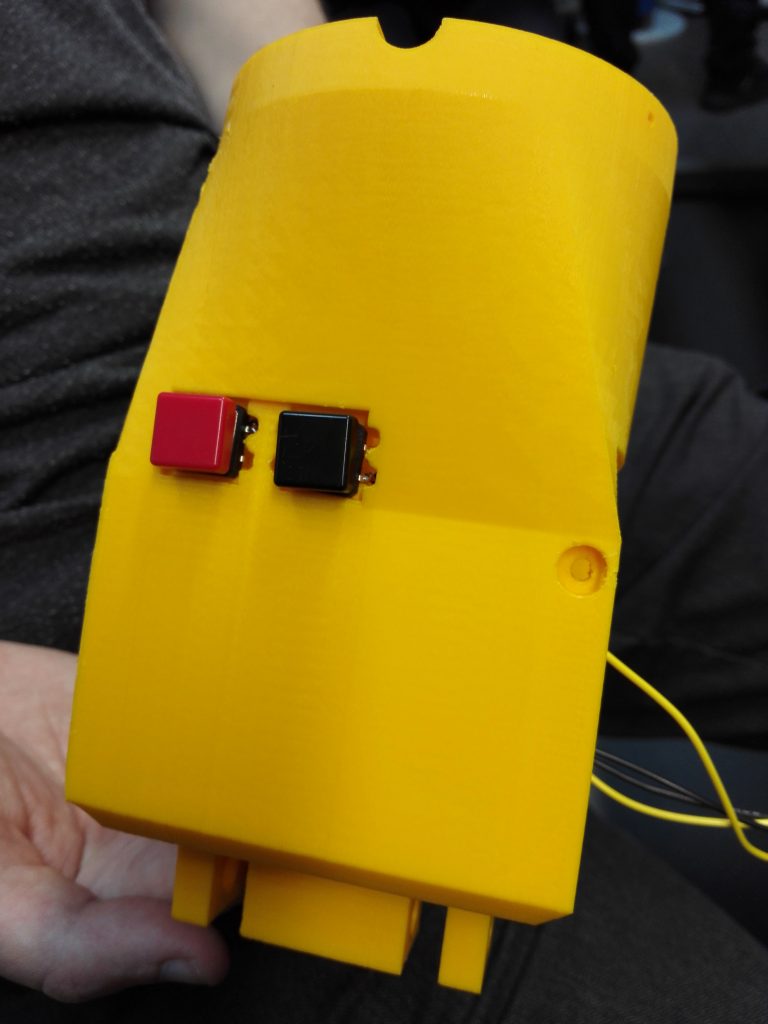
- 2 momentary buttons for manual control.
- Ball bearing. While not strictly needed, it gives support to the rod.
- Various screws and nuts for assembly.
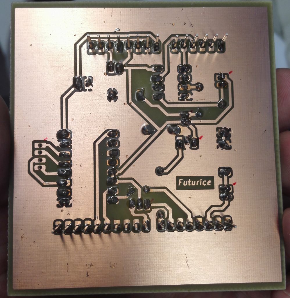
- Capacitors, resistors and headers for the PCB.
- 1 power supply that is suitable for your motor.
- Jump wires.
- 3D printed parts:
Tools
-
- Screwdrivers, knives, cutters
- 3D printer
- Lathe
- Drill
- Turning
- A computer for uploading the code to the Arduino board and USB wire
Manufacturing
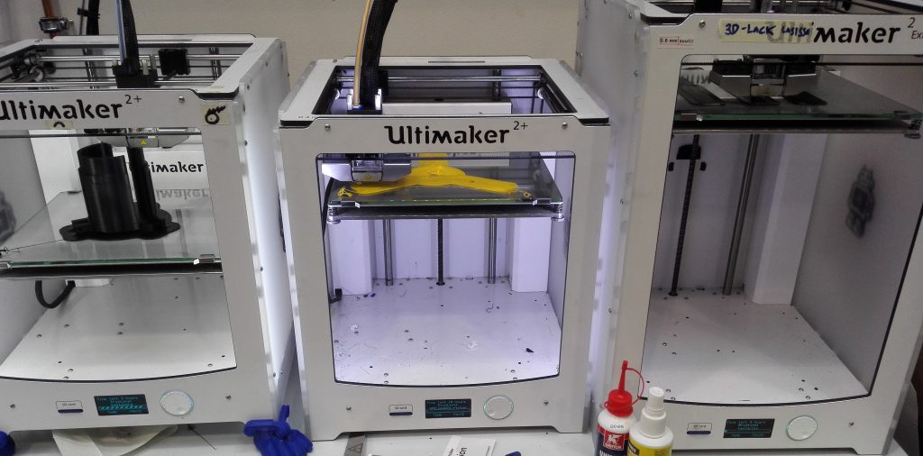
Print the parts
Start constructing the hand by printing all the parts. This will take a significant amount of time. After finishing, remove support material from the holes of each part and polish them if you want.
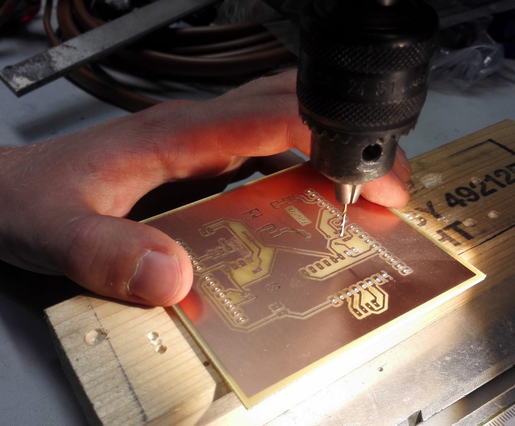
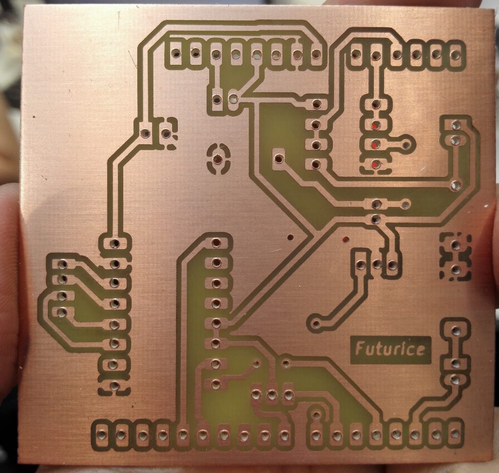
Manufacture the PCB
Manufacture the PCB for the robot hand, or have it ordered from somewhere. Drill the holes for the component legs. Solder components and headers to the board. Remember to check for the order of the headers.
Manufacture rod attachment
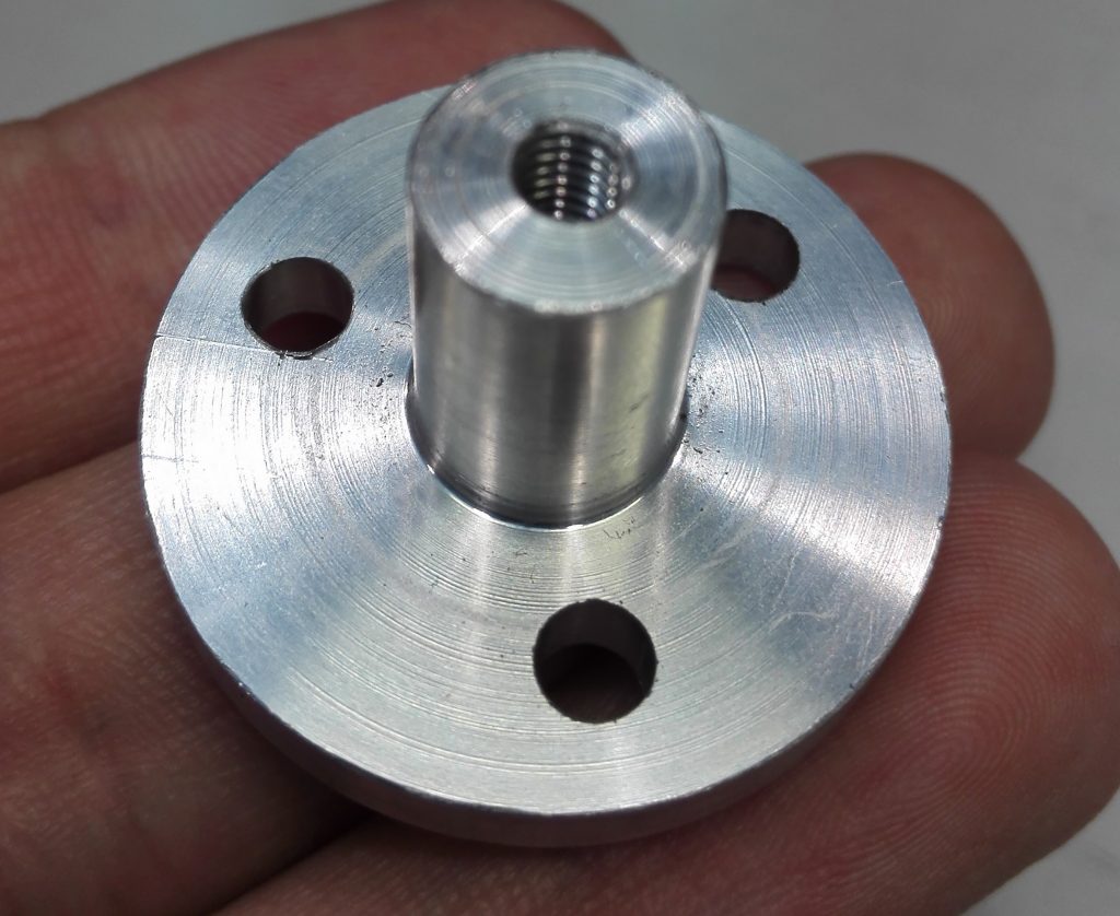
The threaded rod needs a threaded attachment part in the center of the piston. We manufactured this from aluminium through lathing, turning and drilling. The turning should remove the material from the cast approximated 0.5 mm each time. For last few turns should be removed 0.1 mm each time so that you can have a fit attachment. For example, in our process, the part has a designed diameter of 10 mm, the printed piston, however, has a little smaller hole and the machined part was then 9.9 mm in diameter which was perfectly fit the hole.
Make sure that the threads you make in the piece match the threads of your rod! The rod can be of your choice. However, we recommend an M4 rod since a smaller rod can easily bend when a big size rod slows down the speed.
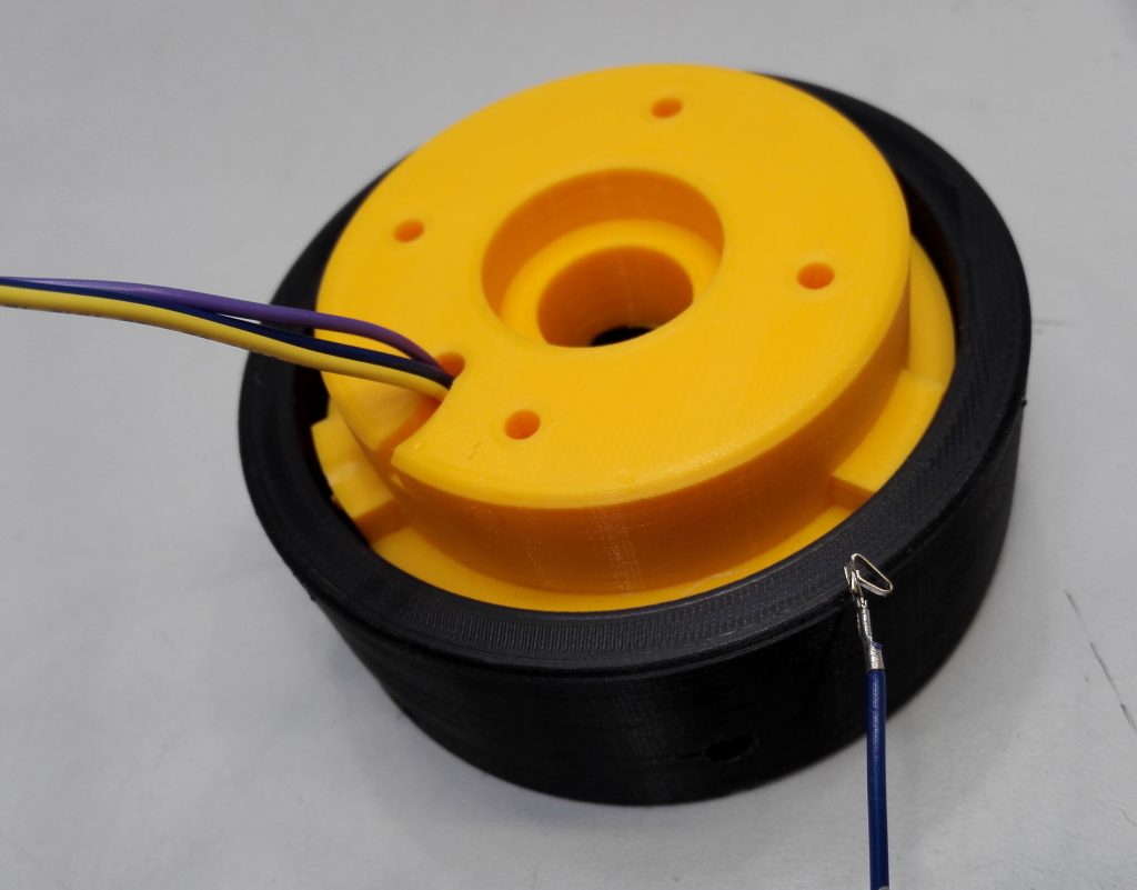
Assembly
A word of warning: The assembly order was not really in our mind when the individual parts were being designed, so there are some difficulties in the assembly!
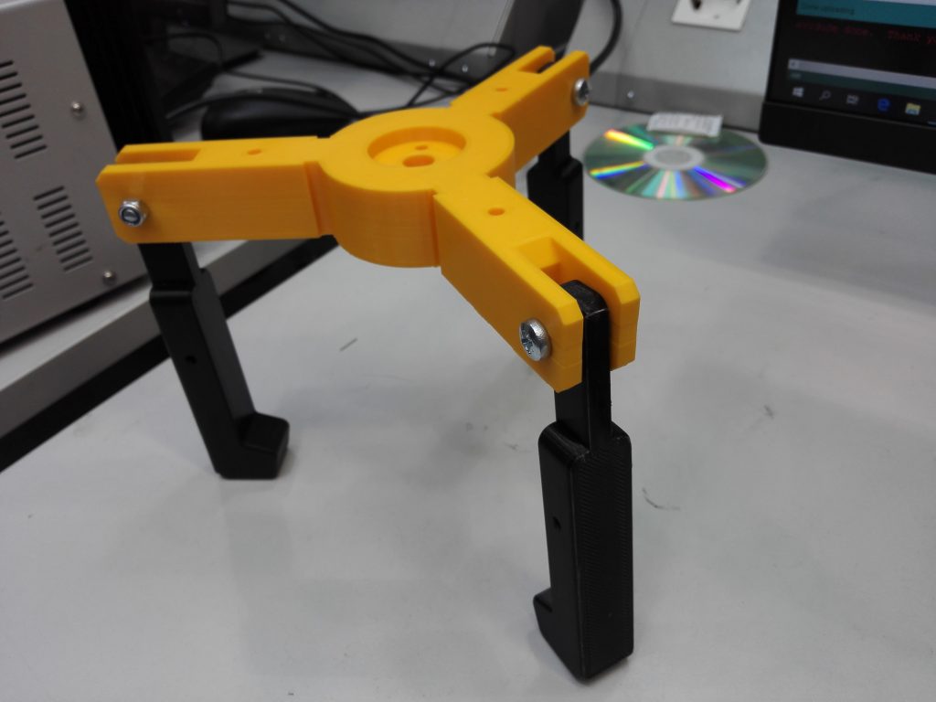
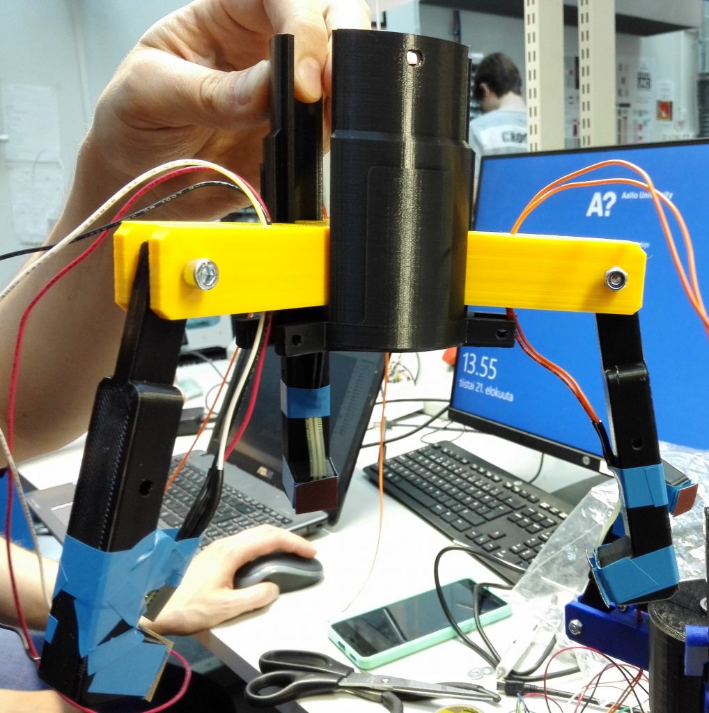
Fingers & Piston
-
- Attach the three fingers to the center piston with screws and nuts.
- Attach the lathed part to the piston with screws and nuts.
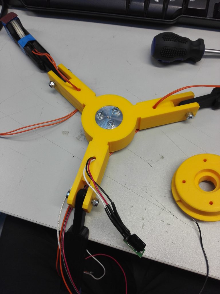
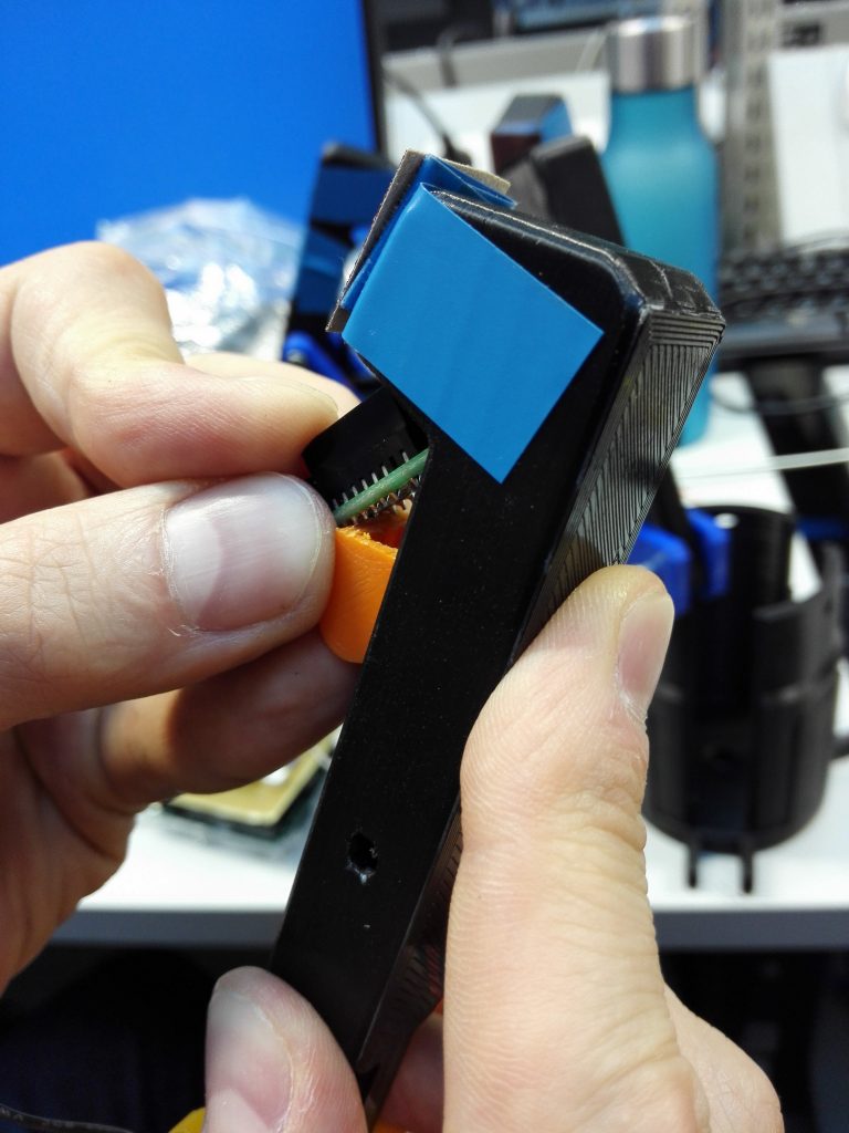
- Attach the sensors to the fingers (test the sensors before attaching them, otherwise you will have more laborious work).
- Run the sensor wires through the holes in the piston.
-
-
-
-
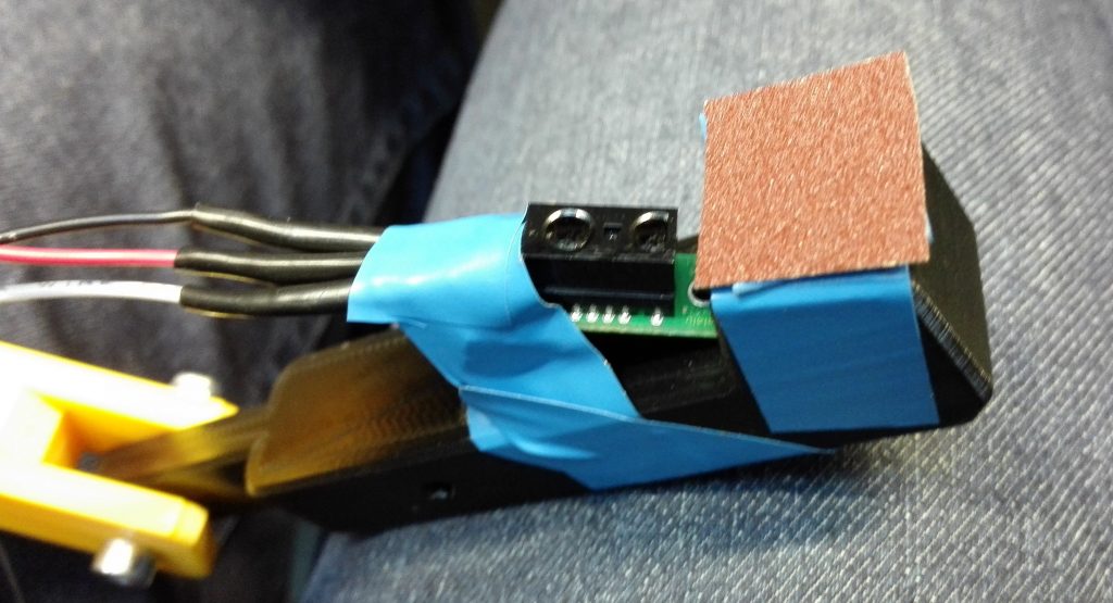
- For the pressure sensor:
- A layer of electrical tape on the finger.
- The sensor on top of the tape.
- Another layer of tape on top of the sensor.
- Double-sided tape on top of the previous layers.
- A piece of sandpaper topmost for gripping friction.
- For the infrared sensor:
- Put the sensor as close as possible to the fingertip.
- Aim the sensor so that it points right past the fingertip.
- Use a piece of plastic to wedge the sensor to its position.
- Attach with tape.
- For the pressure sensor:
-
-
-
-
-
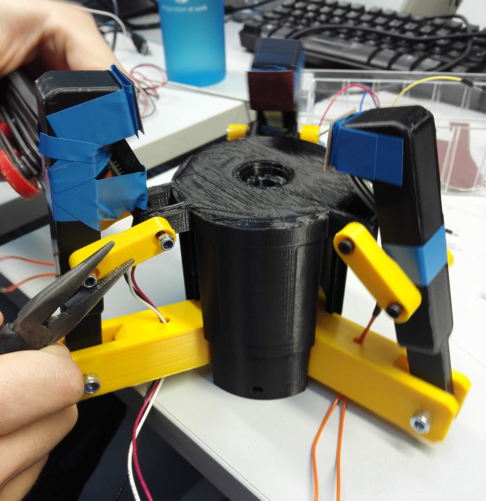
- Slide the piston into the enclosure.
- Attach the finger middle pieces to their places in the enclosure and fingers.
-
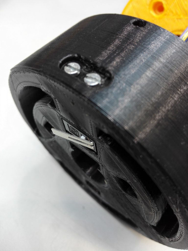
Endstop
-
-
- Solder wires to the endstop button.
- Screw the endstop to its place in the hat.
- Insert the endstop wires through the hole in the motor attachment.
-
DO NOT screw the motor attachment to the hat yet!
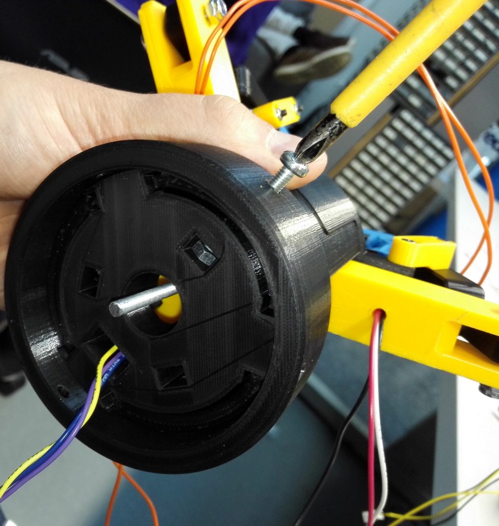
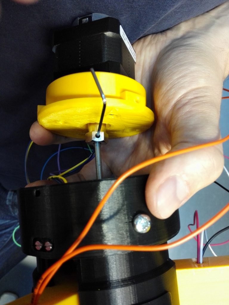
Motor & Rod
-
- Attach rod to center piston by spinning it through the lathed attachment piece. If possible, do not leave the piston to the bottom position (or move the motor later to lift the piston to allow assembly of hat properly).
- Attach the hat to the enclosure.
- Attach the motor to the motor attachment piece.
- Attach the threaded rod to the motor.
- Run the motor (slowly) so that the piston moves enough that you can attach the motor attachment to the hat without leaving a gap.
- Attach motor attachment to the hat with screws.
- Put the ball bearing to the palm of the robot, screw a nut to attach the rod to the bearing. Spinning the motor can help with this. If the rod is too long, cut the extra piece away.
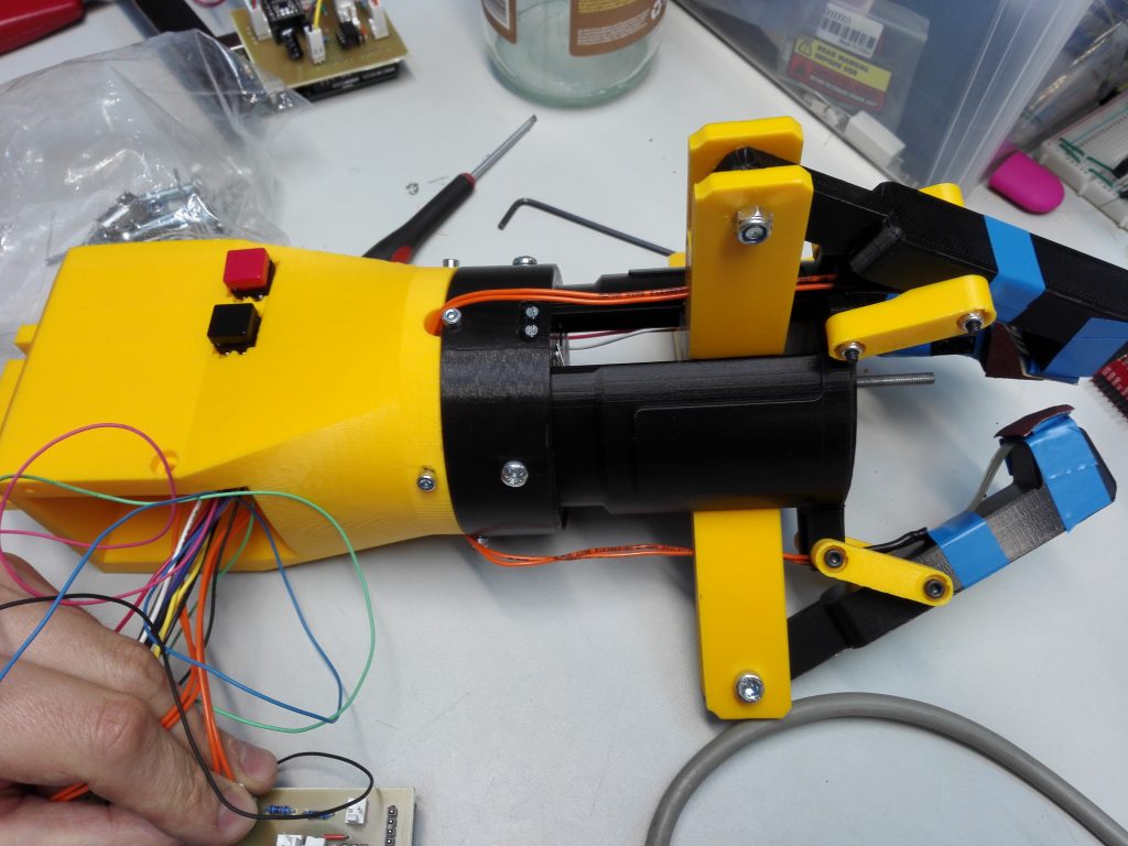
Wrist
-
- Solder wires for the buttons.
- Put the buttons into their place in the wrist piece.
- Screw the wrist to the rest of the robot. Run all the wires coming from the robot through the hole in the wrist part.
- Attach wires to their places on the PCB.
- Stick all the electronics in the compartment in the wrist.
- Close the lid of the electronics compartment.
- Attach the handle.
Your grabber is now ready and hopefully functional!
Results
The end result should be a three-fingered robot hand capable of crushing objects, but with accurate enough feedback to prevent it from accidentally doing so.
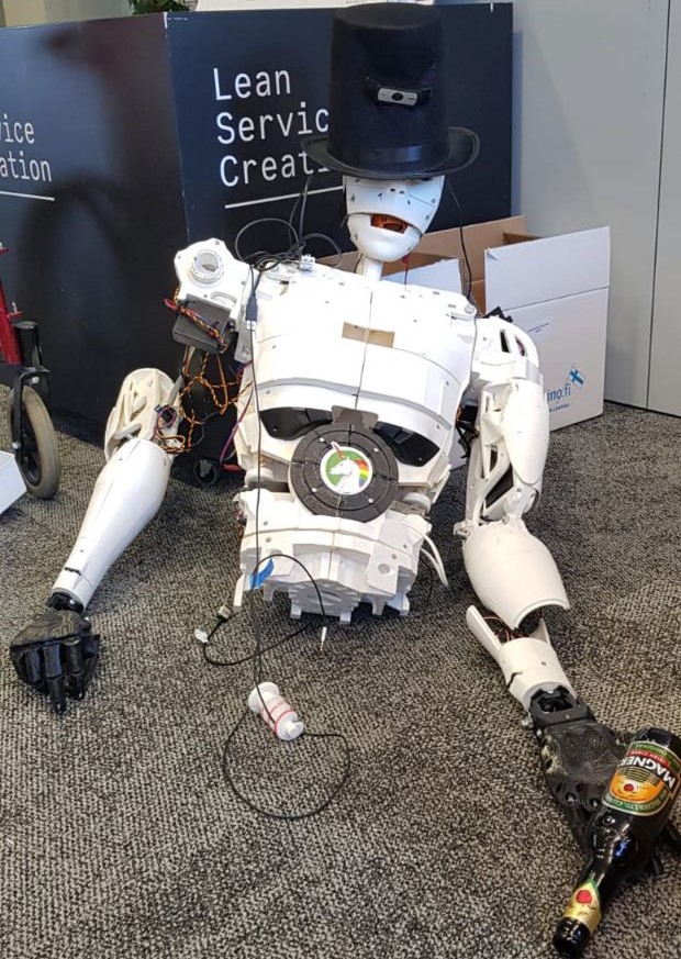
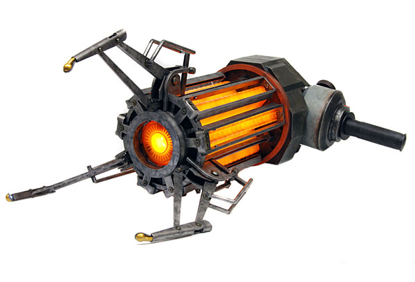
The end result looks a bit like the “Gravity Gun” from the video-game Half-Life 2.
Hence our prototype was named “The Grabbity Gun”.
Problems and cautions
The infrared sensor can only detect the presence of an object within a limit 0.5 – 5 cm. The position of the sensor should be adjusted so that the grasping object never stays so close the sensor. Otherwise, the sensor will yield an unstable signal and the hand cannot properly grasp the object.
It is recommended to manually test the functionality of the motor driver and endstop before using the main code (click on the link to find the source code file which should be “.ino” files). This step prevents damaging the motor or disconnection between the motor shaft and the threaded rod.
Credits and Licensing
The project made by:
-
-
-
-
-
-
- Joel Määttänen
- Ville Sinkkonen
- Lauri Blomberg
- Minh Nguyen
- Jani Kiviaura
-
-
-
-
-
License:
CODE: MIT-license
OTHER: Creative Commons (CC) BY 4.0